Category: Manuals Page 1 of 3

porter cable compressor 150 psi manual

Porter Cable 150 PSI Compressor Manual: A Comprehensive Guide

This manual details the operation, maintenance, and troubleshooting of your Porter Cable 150 PSI compressor, ensuring optimal performance and longevity.
It leverages insights from resources like the Internet Archive, focusing on models such as the C2002, and provides a masterful control experience.

Porter Cable 150 PSI compressors are renowned for their reliability and versatility, serving as essential tools for a wide array of applications – from DIY projects to professional construction. These compressors deliver substantial air power, capable of driving nail guns, impact wrenches, spray painters, and various pneumatic tools.

Understanding your compressor is paramount for safe and efficient operation. This introduction sets the stage for a comprehensive guide, covering everything from model specifics (like the popular C2002) to detailed maintenance procedures. The Internet Archive highlights the importance of preserving information, and this manual aims to do just that – providing a lasting resource for Porter Cable compressor owners.

Whether you’re a seasoned professional or a first-time user, this guide will empower you to maximize the performance and lifespan of your 150 PSI compressor, ensuring it remains a dependable asset for years to come.

Understanding Compressor Models (C2002 & Similar)

Porter Cable offers a range of 150 PSI compressors, with the C2002 being a particularly popular and widely used model. Similar models, like the C2002-WK, share core components and operational principles, but may include variations in accessories or features. Key distinctions often lie in tank capacity, horsepower, and the inclusion of features like wheel kits for enhanced portability.

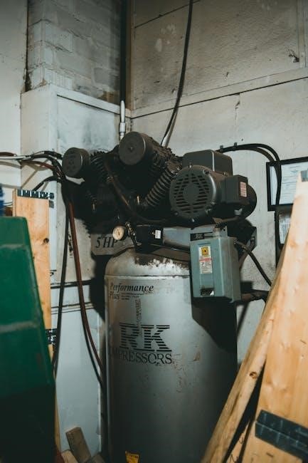
The C2002 typically features a 6-gallon tank, providing ample air storage for various tasks. Understanding the specific model number is crucial for sourcing the correct replacement parts and accessing tailored documentation. Resources like parts diagrams, often found through online archives, are invaluable for identifying components.

This guide will primarily focus on the C2002 as a representative example, but the principles discussed apply broadly to other 150 PSI Porter Cable compressors. Recognizing these similarities streamlines maintenance and troubleshooting across the product line.

Safety Precautions & Warnings

Prioritize safety when operating your Porter Cable 150 PSI compressor. Always wear appropriate eye and ear protection to shield against debris and noise. Never operate the compressor without all safety guards and covers securely in place. Ensure the compressor is grounded to prevent electrical shock, and inspect the power cord for damage before each use.

Never exceed the maximum pressure rating of 150 PSI. Regularly inspect the tank for signs of rust or damage, and do not use a compromised tank. Avoid modifying the compressor in any way, as this could compromise its safety features. Keep the work area clean and well-ventilated, and never direct airflow towards yourself or others.

Disconnect the power supply before performing any maintenance or repairs. Allow the tank to fully depressurize before draining. Refer to the complete manual for detailed safety guidelines and warnings.

Key Components & Their Functions

Understanding the core elements—tank, pump, motor, pressure switch, and check valve—is crucial for effective operation and maintenance of your Porter Cable compressor.

The Tank: Capacity & Pressure Rating

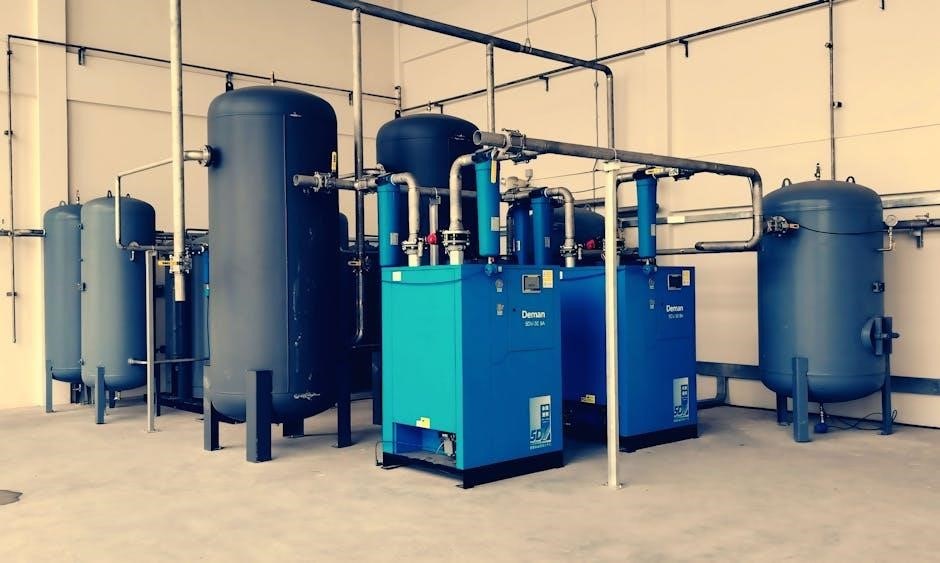
The compressor tank is the heart of stored energy, providing a reserve of compressed air for various pneumatic tools. Porter Cable 150 PSI compressors typically feature tanks ranging in capacity from 6 to 30 gallons, influencing the duration of tool use before the motor cycles on to replenish pressure.

Crucially, the tank is engineered with a maximum pressure rating of 150 PSI; exceeding this limit poses a significant safety hazard. Regular inspection for rust, corrosion, or damage is paramount. The tank’s capacity directly impacts the air volume available for operation, while the pressure rating dictates the maximum force with which air can be delivered.

Always ensure the tank drain valve functions correctly to prevent moisture buildup, which can lead to corrosion and reduce tank lifespan. Understanding your specific model’s tank specifications, found in the manual, is vital for safe and efficient operation.

The Pump: Oil-Free vs. Oil-Lubricated

Porter Cable 150 PSI compressors utilize two primary pump types: oil-free and oil-lubricated. Oil-free pumps are favored for their lower maintenance requirements, eliminating the need for regular oil changes and reducing mess. However, they generally have a shorter lifespan and can be louder during operation due to increased friction.

Oil-lubricated pumps, conversely, employ oil to coat internal components, minimizing friction, reducing wear, and extending the pump’s overall life. They operate more quietly but necessitate periodic oil checks, changes, and proper disposal. The choice depends on usage frequency and tolerance for maintenance.

Understanding your compressor’s pump type is crucial for proper care. Refer to your model’s documentation for specific oil recommendations (if applicable) and maintenance schedules. Ignoring these guidelines can lead to premature pump failure and void the warranty.

Motor Specifications & Overload Protection

Porter Cable 150 PSI compressors are equipped with robust motors designed for reliable performance. Typical specifications include a voltage of 120V and a horsepower rating ranging from 1.5 to 2.5 HP, depending on the model. Amperage draw is a critical factor when selecting extension cords – ensure the cord’s rating exceeds the compressor’s requirements.

Crucially, these compressors incorporate overload protection. This safety feature automatically shuts off the motor if it overheats due to excessive strain or prolonged use. Repeated tripping of the overload protector indicates a potential issue, such as a blocked air filter or insufficient ventilation.

Allow the motor to cool completely before resetting the overload button, typically located near the motor housing. Ignoring this can cause further damage. Always ensure adequate airflow around the compressor to prevent overheating and maintain optimal motor function.

Pressure Switch: Operation & Adjustment

The pressure switch is the brain of your Porter Cable 150 PSI compressor, controlling when the motor starts and stops to maintain desired air pressure. It operates based on two pressure settings: cut-in and cut-out. The cut-in pressure initiates the motor when the tank pressure drops, while the cut-out pressure shuts it off when the maximum pressure is reached.

Adjustment is typically achieved via screws or knobs on the switch itself. Caution: Adjustments should only be made by qualified individuals. Increasing the cut-out pressure allows for higher maximum pressure, but also increases stress on the system. Conversely, lowering it reduces pressure but may lead to frequent motor cycling.

Always disconnect power before attempting any adjustments. Improper settings can compromise safety and damage the compressor. Regularly inspect the switch for corrosion or damage, as this can affect its functionality and potentially create a hazard.

Check Valve: Function & Maintenance

The check valve is a crucial component in your Porter Cable 150 PSI compressor, ensuring air flows in only one direction – from the pump into the tank. This prevents backflow, maintaining pressure even when the pump isn’t running. It’s typically located between the pump and the tank.

Regular maintenance is vital for optimal performance. Over time, debris and contaminants can accumulate, causing the valve to stick or leak. This results in reduced efficiency and potentially prevents the tank from reaching its maximum pressure.

Inspect the check valve periodically for signs of corrosion or damage. Cleaning can sometimes resolve minor issues, but replacement is often necessary for severely affected valves. Disconnect the power supply before any inspection or maintenance. A faulty check valve can significantly impact compressor functionality.

Operating Instructions

Proper operation involves initial setup, priming (if needed), pressure adjustments, and utilizing the quick connect coupler for efficient tool connections and airflow control;

Initial Setup & Power Connection

Before first use, carefully inspect the Porter Cable compressor for any shipping damage. Ensure all components are present, referencing the C2002 parts diagram if necessary. Position the compressor on a stable, level surface with adequate ventilation, avoiding confined spaces.

Connect the appropriate power cord – verify it matches your local voltage requirements. Never use an extension cord unless absolutely necessary, and if so, use a heavy-duty cord rated for the compressor’s amperage.

Confirm the pressure switch is in the ‘OFF’ position before plugging in the unit. Avoid accidental starting. Double-check all fittings are tight, and the drain valve is closed. The compressor is now ready for initial operation, but priming may be required depending on the model – consult the pump section for details.

Priming the Pump (If Applicable)

Not all Porter Cable 150 PSI compressors require priming; this step primarily applies to oil-lubricated models, particularly after extended periods of inactivity or initial setup. Priming ensures adequate lubrication for the pump’s internal components, preventing damage during startup.

To prime, locate the oil fill plug – typically on the pump housing. Remove the plug and slowly pour in the recommended compressor oil, ensuring it reaches the appropriate level as indicated by the dipstick.

Plug the compressor in and briefly activate it (less than 10 seconds) to circulate the oil. Repeat this process a few times, checking the oil level each time, until the pump is adequately primed. Do not run the compressor continuously during priming. Refer to the oil-lubricated pump section for specific oil type recommendations.

Adjusting Pressure & Airflow

Your Porter Cable 150 PSI compressor features adjustable pressure and airflow settings, allowing customization for various tools and applications; The pressure is controlled via the pressure switch, typically with a dial or adjustable screws. Turning the adjustment screw clockwise increases pressure, while counterclockwise decreases it.

Always ensure the compressor is disconnected from power before adjusting the pressure switch. Start with a lower pressure setting and gradually increase it until the desired level is reached. Monitor the pressure gauge to confirm accurate adjustments.

Airflow is indirectly controlled by the compressor’s output capacity and the tool’s air consumption. Using a regulator inline with your air tool allows for fine-tuning of airflow to match the tool’s requirements, optimizing performance and preventing damage.

Using the Quick Connect Coupler

The quick connect coupler on your Porter Cable 150 PSI compressor allows for rapid attachment and detachment of air hoses and tools. Before connecting, ensure the compressor is turned off and the tank has depressurized. Push the air hose firmly into the coupler until it clicks, indicating a secure connection.

To disconnect, simply pull back the coupler sleeve; this releases the pressure and allows for easy hose removal. Avoid disconnecting while the compressor is pressurized, as this can cause a burst of air and potential injury. Regularly inspect the coupler for damage or debris.

Using a high-quality air hose with compatible fittings is crucial for optimal performance and preventing leaks. Ensure the hose is rated for the compressor’s maximum pressure. Proper use extends the life of both the coupler and your air tools.

Maintenance & Troubleshooting

Regular maintenance ensures peak performance and extends the life of your Porter Cable compressor. Addressing issues promptly prevents costly repairs and downtime, maintaining operational efficiency.

Daily Maintenance Checks

Before each use, a quick inspection of your Porter Cable 150 PSI compressor is crucial for safe and efficient operation. Begin by visually examining the air hose for any cracks, abrasions, or leaks. Ensure all fittings are securely connected and tightened to prevent air loss during operation.

Check the oil level (for oil-lubricated models) using the dipstick, adding oil if necessary to maintain the proper level. Listen for any unusual noises during the initial startup, which could indicate a potential problem with the pump or motor. Verify that the pressure gauge reads accurately and that the pressure switch is functioning correctly.

Inspect the air filter for dirt and debris, cleaning or replacing it as needed to ensure adequate airflow to the pump. Finally, confirm that the drain valve is accessible and functioning properly for easy tank draining. These simple daily checks will help identify and address minor issues before they escalate into major repairs.

Draining the Tank: Importance & Procedure

Regularly draining the tank of your Porter Cable 150 PSI compressor is paramount to prevent corrosion and maintain optimal performance. Moisture buildup within the tank can lead to rust, reducing tank capacity and potentially causing internal damage.

To drain the tank, first, disconnect the compressor from the power source and release any remaining air pressure by opening the pressure relief valve. Locate the drain valve, typically at the bottom of the tank. Carefully open the drain valve and allow all accumulated water to drain completely.

A small amount of air may escape during this process. Once the water flow stops, close the drain valve securely. This procedure should be performed daily, especially after periods of heavy use or in humid environments. Consistent draining extends the life of your compressor and ensures clean, dry air for your tools.

Oil Changes (For Oil-Lubricated Models)

Maintaining proper oil levels and performing regular oil changes are crucial for the longevity of oil-lubricated Porter Cable 150 PSI compressors. Oil provides essential lubrication, reducing friction and wear on internal components like the piston and cylinder.

Consult your specific model’s manual for the recommended oil type and change interval – typically every 200-300 hours of operation. Before changing the oil, disconnect the compressor from the power source and release all air pressure. Locate the oil drain plug, usually at the bottom of the crankcase, and carefully remove it, allowing the old oil to drain completely into a suitable container.

Replace the drain plug with a new one if necessary, and then refill the crankcase with the recommended oil to the specified level. Always dispose of used oil responsibly, following local regulations.

Troubleshooting Common Issues: No Pressure, Leaks, Overheating

Addressing common issues promptly will keep your Porter Cable 150 PSI compressor running efficiently. If the compressor builds no pressure, check the power supply, pressure switch settings, and for any tripped circuit breakers. Air leaks can occur at fittings, hoses, or the tank itself; tighten connections or replace damaged parts.

Overheating often indicates insufficient ventilation, a faulty pressure switch, or low oil levels (in oil-lubricated models). Ensure the compressor is in a well-ventilated area and isn’t obstructed. Inspect the pressure switch for proper operation and verify adequate oil levels.

Always disconnect the power before inspecting or repairing any component. If problems persist, consult a qualified technician. Remember, regular maintenance, as outlined in this manual, can prevent many of these issues.

Replacing Air Filter

Maintaining a clean air filter is crucial for optimal compressor performance and longevity. A clogged filter restricts airflow, causing the pump to work harder and potentially overheat. Replacement frequency depends on usage and environment, but inspect it monthly and replace as needed.

To replace the air filter, first disconnect the power supply to the compressor. Locate the air filter housing, typically near the pump intake. Open the housing and remove the old filter, noting its orientation. Clean the housing interior of any debris.

Install the new air filter, ensuring it’s properly seated and oriented correctly. Securely close the filter housing. Reconnect the power and resume operation. A clean air filter ensures efficient cooling and extends the life of your Porter Cable compressor.

Parts & Accessories

Genuine Porter Cable replacement parts and compatible accessories are essential for maintaining your 150 PSI compressor’s performance and ensuring safe, reliable operation.

Common Replacement Parts (C2002 Parts Diagram)

Maintaining your Porter Cable C2002 compressor often requires replacing worn components. Frequently needed parts include the air filter, crucial for clean airflow and preventing damage to internal mechanisms. The pressure switch, responsible for regulating tank pressure, may need replacement if it fails to maintain set levels.

Check valves, preventing backflow, and rubber feet, reducing vibration, are also common replacements. The motor, while durable, can require brushes or complete replacement over time. Hoses and fittings are prone to wear and tear, necessitating periodic changes.

A detailed C2002 parts diagram is invaluable for identifying the correct components. These diagrams, often available online or through Porter Cable’s support channels, illustrate each part’s location and corresponding part number, simplifying the repair process and ensuring compatibility. Always refer to the diagram when ordering replacements.

Air Hose & Fittings

Selecting the right air hose and fittings is vital for safe and efficient operation of your Porter Cable 150 PSI compressor. Hoses should be rated for at least 150 PSI, matching the compressor’s maximum output, and constructed from durable materials like rubber or polyurethane to withstand abrasion and weather conditions.

Common fitting types include NPT (National Pipe Thread) and quick-connect couplers, facilitating easy tool attachment. Ensure compatibility between hose and fitting sizes to prevent leaks. Consider hose length based on your workspace; longer hoses offer greater reach but may reduce airflow.

Regularly inspect hoses for cracks, kinks, or damage, replacing them immediately if found. Properly secure fittings to prevent accidental disconnection during use. Using high-quality hoses and fittings enhances performance and extends the lifespan of your compressor system.

Pressure Gauges & Regulators

Pressure gauges and regulators are crucial components for controlling and monitoring air pressure within your Porter Cable 150 PSI compressor system. Gauges display the tank pressure and regulated output pressure, allowing for precise adjustments. Regulators reduce the high pressure from the tank to a usable level for various tools, preventing damage and ensuring optimal performance.

Understanding the difference between tank pressure and regulated pressure is key. Tank pressure indicates the stored energy, while regulated pressure determines the airflow to your tools. Regularly check gauge accuracy and calibrate if necessary;

Adjust the regulator to match the tool’s recommended pressure setting. A faulty regulator can cause inconsistent airflow or over-pressurization, potentially leading to tool failure or injury. Maintaining these components ensures safe and efficient operation.

Filter/Regulator Combinations

Filter/regulator combinations streamline your Porter Cable 150 PSI compressor setup, offering both air filtration and pressure regulation in a single unit. These integrated systems remove moisture and debris from the compressed air, protecting your tools and extending their lifespan. The regulator allows precise control over output pressure, adapting to various tool requirements.

Regular maintenance of these combination units is vital. Periodically drain the filter bowl to remove accumulated water, preventing corrosion and ensuring clean air delivery. Check the filter element for clogging and replace it as needed.

A properly functioning filter/regulator combination enhances air tool performance and reliability. Ignoring maintenance can lead to reduced airflow, tool malfunction, and potential safety hazards. Ensure optimal operation by following recommended service intervals.

uniden walkie talkie user manual

Uniden Walkie Talkie User Manual: A Comprehensive Guide

Discover essential guides, specifications, and troubleshooting for Uniden GMR-1635-2 and Bearcat models, alongside downloadable PDF manuals and operational assistance.

Uniden walkie talkies represent a long-standing tradition of reliable communication, serving diverse needs from recreational outdoor adventures to professional security applications. This comprehensive guide focuses on maximizing your Uniden experience, specifically addressing models like the GMR-1635-2 and various Bearcat series.

Whether you’re a first-time user or seeking to unlock advanced features, this manual provides clear instructions on setup, operation, and troubleshooting. You’ll find details on accessing downloadable PDF manuals, understanding channel configurations, and optimizing performance.

Uniden offers a range of radios, not intended as toys for children, and this guide aims to empower users with the knowledge to utilize their full potential. We’ll cover everything from battery installation to advanced functionalities like VOX and channel scanning.

Understanding Key Features

Uniden walkie talkies boast a variety of features designed for clear and dependable communication. Key among these are the FRS/GMRS channel options, offering both license-free and extended-range capabilities. Many models, like the GMR-1635-2, include 22 channels plus weather radio access, providing crucial updates during outdoor activities.

Scanning functionality allows for automatic channel searching, quickly locating active conversations. VOX (Voice Operated Exchange) enables hands-free operation, ideal for situations where manual button presses are impractical. Understanding these features, detailed in downloadable PDF manuals, is crucial for optimal performance.

Furthermore, features like channel codes and robust build quality contribute to Uniden’s reputation. Proper antenna attachment and battery installation are fundamental to maximizing range and clarity.

Uniden GMR-1635-2: Overview and Specifications

The Uniden GMR-1635-2 is a popular walkie talkie model offering both FRS and GMRS capabilities, expanding communication range. It features 22 channels, including NOAA weather radio for emergency broadcasts. This two-way radio is designed for recreational use, providing reliable connectivity for outdoor adventures and family activities.

Specifications include a range of up to 30 miles (depending on terrain), selectable power output levels, and a backlit LCD display for easy visibility. The GMR-1635-2 supports VOX operation and channel scanning. Detailed specifications and operational guidance are available in the owner’s manual, often found as a downloadable PDF.

It’s important to note this isn’t a toy; it’s a communication device for responsible users.

Setting Up Your Uniden Walkie Talkie

Before first use, proper setup is crucial for optimal performance. Begin by carefully reviewing the included owner’s manual, often available as a downloadable PDF. Initial setup involves installing batteries – ensure correct polarity for each unit. Next, securely attach the antennas; a proper connection maximizes signal range and clarity.

Familiarize yourself with the radio’s controls, including power, volume, and channel selection. The manual details these functions. Consider the environment; clear line of sight improves communication. Understanding these initial steps will ensure a smooth and effective user experience with your Uniden walkie talkie.

Always refer to the manual for model-specific instructions.

Installing Batteries

Proper battery installation is fundamental for your Uniden walkie talkie’s operation. Most models require either AA or AAA batteries, though some utilize rechargeable battery packs. Always check your specific model’s manual for the correct battery type and quantity.

When inserting batteries, carefully observe the polarity markings (+ and -) within the battery compartment. Incorrect installation can damage the radio and void the warranty. Ensure the battery contacts are clean and free of corrosion for optimal conductivity.

For rechargeable packs, follow the charging instructions detailed in the manual. Fully charge before initial use. Regularly check battery levels and replace or recharge as needed for consistent performance.

Attaching Antennas

Securely attaching the antenna is crucial for maximizing your Uniden walkie talkie’s range and signal clarity. Most models feature a standard antenna connector; gently screw the antenna onto the connector, ensuring it’s snug but not overtightened. Avoid forcing the antenna, as this could damage the connector.

The antenna should be held upright for optimal transmission and reception. Avoid bending or damaging the antenna, as this will significantly reduce performance. If your model supports antenna upgrades, consult the manual for compatible options.

Regularly inspect the antenna connection for looseness. A properly connected antenna is vital for reliable communication.

Basic Operations

Understanding the fundamental operations of your Uniden walkie talkie ensures effective communication. Begin by familiarizing yourself with the power button, volume control, and channel selection dial. These are the core controls for basic functionality.

Before use, ensure the antenna is securely attached. Proper antenna connection is vital for signal strength. Once powered on, adjust the volume to a comfortable level. Experiment with different channels to find the clearest signal in your area.

Practice transmitting and receiving with another user to confirm proper operation. Remember to press the ‘push-to-talk’ button before speaking.

Powering On and Off

To initiate operation, locate the power button – typically a clearly marked button on the front or side of the Uniden walkie talkie. Press and hold this button for a few seconds until you observe a visual indicator, such as an illuminated screen or a power-on sound.

Conversely, to conserve battery life when not in use, press and hold the same power button again. The device will power down, indicated by the screen going blank or the sound ceasing.

Always ensure the device is fully powered off when storing it for extended periods to prevent accidental battery drain.

Adjusting Volume

Controlling the audio level on your Uniden walkie talkie is crucial for clear communication. Typically, volume adjustment is managed via dedicated up and down buttons, or a rotating dial, located on the device’s front panel.

Pressing the ‘up’ button increases the speaker volume, while the ‘down’ button decreases it. Begin with a low volume setting and gradually increase it until the audio is comfortably audible.

Be mindful of your surroundings; excessively high volume can be disruptive. Some models also feature a mute function for instant silence. Experiment to find the optimal volume for various environments.

Channel Selection

Choosing the correct channel is vital for successful communication with other Uniden walkie talkie users. Your device likely offers a range of FRS and GMRS channels, each potentially serving different purposes or user groups.

Channel selection is usually accomplished using up and down arrow buttons, or a channel selector dial. Refer to the channel chart in your user manual to understand the designated use for each channel.

Ensure all radios in your party are set to the same channel for direct communication. Be aware of potential interference on crowded channels and consider switching to a less congested frequency.

Advanced Features

Uniden walkie talkies boast features extending beyond basic transmission. Understanding these unlocks enhanced usability. Explore the differences between FRS (Family Radio Service) and GMRS (General Mobile Radio Service) channels; GMRS often requires licensing for higher power transmission.

The scanning function automatically searches for active channels, halting on any detected signal. This is useful for locating nearby conversations. VOX (Voice Operated Exchange) allows hands-free operation – the radio transmits when it detects your voice.

Familiarize yourself with channel codes for added privacy, though they don’t guarantee secure communication. These features elevate your walkie-talkie experience.

FRS/GMRS Channels Explained

FRS (Family Radio Service) channels are license-free, offering convenient short-range communication. They operate at lower power, ideal for recreational use like hiking or family outings. However, range is limited.

GMRS (General Mobile Radio Service) channels require an FCC license but allow for higher power output and the use of repeater systems, significantly extending the communication range. This makes GMRS suitable for longer distances or challenging terrain.

Uniden walkie talkies often support both FRS and GMRS. Understanding these distinctions is crucial for legal and effective operation. Check the specific model’s capabilities and licensing requirements before use.

Scanning Channels

Channel scanning allows your Uniden walkie talkie to automatically search for active transmissions across all programmed channels. This feature is incredibly useful for monitoring activity without manually cycling through each channel.

To initiate a scan, typically you’ll press a dedicated “Scan” button. The radio will pause briefly on any channel where activity is detected. If you wish to respond, press the Push-to-Talk (PTT) button while stopped on that channel.

Scanning prioritizes channels with ongoing communication. Be aware that continuous scanning can reduce battery life. Some models offer customizable scan lists, allowing you to exclude specific channels.

VOX (Voice Operated Exchange) Functionality

VOX, or Voice Operated Exchange, enables hands-free communication with your Uniden walkie talkie. When activated, the radio transmits automatically when it detects sound – your voice – eliminating the need to press the Push-to-Talk (PTT) button.

VOX levels are adjustable, controlling the sensitivity required to initiate transmission. Higher sensitivity detects quieter sounds, while lower sensitivity requires louder speech. Proper adjustment minimizes unwanted transmissions from background noise.

To use VOX, ensure it’s enabled in the radio’s menu. Consider using a compatible headset with a microphone for optimal performance. Be mindful of potential false activations in noisy environments.

Troubleshooting Common Issues

Encountering problems with your Uniden walkie talkie? This section addresses frequent concerns. If your radio has no power, verify battery installation and charge levels. Ensure the batteries are correctly oriented and fully charged, or replace them if necessary.

Poor reception can stem from several factors. Confirm you’re on the correct channel and haven’t exceeded the radio’s range. Obstacles like buildings and terrain can interfere with signals. Try adjusting the antenna for optimal reception.

Refer to the full manual for detailed troubleshooting steps and further assistance. Remember to check for updated firmware or support resources online.

No Power

If your Uniden walkie talkie fails to power on, begin with the basics. First, meticulously check the battery compartment. Ensure batteries are installed with the correct polarity – positive and negative terminals aligned as indicated. Confirm batteries are securely seated and making good contact.

Next, verify battery charge levels. Even new batteries may have insufficient charge. Replace batteries with a fresh set of alkaline or rechargeable batteries of the correct type. If using rechargeable batteries, ensure they are fully charged before use.

Finally, inspect the battery contacts within the compartment for any corrosion or debris, cleaning them gently if necessary.

Poor Reception

Experiencing weak or distorted signals with your Uniden walkie talkie? Several factors can contribute to poor reception. First, ensure the antenna is securely attached and fully extended. A loose or retracted antenna significantly reduces range and clarity.

Consider your surroundings. Obstacles like buildings, trees, and hills can obstruct radio waves. Try moving to a higher location or an open area for a clearer signal. Distance from the other radio also plays a crucial role; walkie talkies have limited range.

Finally, verify you’re on the correct channel and that the other radio is also tuned to the same frequency. Interference from other devices can also impact reception.

Safety Information and Precautions

To ensure safe operation of your Uniden walkie talkie, adhere to these guidelines. Avoid using the device during lightning storms, as the antenna can attract strikes. Never attempt to disassemble or modify the unit, as this could result in electric shock or damage.

Keep the walkie talkie away from water and extreme temperatures. Prolonged exposure to heat or moisture can compromise its functionality. These are not toys for children; supervise use to prevent misuse or injury.

Always practice responsible communication and respect the privacy of others. Be mindful of the transmission range and potential for interference. Follow all applicable regulations regarding radio frequency usage.

Uniden Bearcat Models: A Brief Comparison

Uniden Bearcat radios offer a range of features, from basic FRS/GMRS communication to advanced scanning capabilities. Models like the SX307-3C provide 22 FRS channels and weather alerts, ideal for recreational use. For more demanding needs, consider models available on comprehensive operation and repair service manuals – often found on DVDs containing 340+ PDF guides.

The SDS200 is a more sophisticated option, catering to enthusiasts requiring broader scanning functionality. Comparing models involves assessing channel capacity, power output, and included accessories. Bearcat radios are generally not intended for children, emphasizing their focus on serious communication.

Ultimately, selecting the right Bearcat model depends on your specific requirements and intended application.

Resources and Manual Downloads

Access a wealth of information regarding your Uniden walkie talkie through readily available online resources. PDF versions of owner’s manuals, like those for the GMR-1635-2, are frequently accessible for download. Explore online databases offering free PDF files for various Uniden models, including guides for the KG UV3D and TK-372G.

Comprehensive service manuals, often compiled onto DVDs containing hundreds of PDF documents (like the Ultimate Uniden Bearcat collection with 340 manuals), provide detailed repair and operational information. User guides, setup instructions, and troubleshooting assistance for LKPower products are also discoverable.

Don’t hesitate to search for specific model numbers to locate the most relevant documentation.

Understanding Channel Codes

Uniden walkie talkies utilize both FRS (Family Radio Service) and GMRS (General Mobile Radio Service) channels, offering varied communication ranges and capabilities. The SX307-3C model, for instance, features 22 FRS channels, providing license-free, short-range communication. GMRS channels, however, typically require an FCC license for operation, enabling greater power output and extended range.

Channel selection is crucial for avoiding interference. Understanding the designated use for each channel – whether for general use, marine communication, or specific groups – ensures clear transmissions. Some models offer channel scanning to automatically locate active channels.

Proper channel selection enhances communication reliability.

Care and Maintenance

To ensure the longevity and optimal performance of your Uniden walkie talkie, regular care is essential. Clean the device with a damp cloth, avoiding harsh chemicals or abrasive cleaners. Inspect antennas for damage and ensure they are securely attached; loose connections can significantly reduce range.

Proper battery storage is vital. Remove batteries for extended periods of non-use to prevent corrosion. When storing, keep the walkie talkie in a dry, cool place, away from direct sunlight and extreme temperatures. Avoid dropping or subjecting the device to physical shock.

Regular checks and careful handling will maintain reliable communication.

snow blower manual

Snow Blower Manual: A Comprehensive Guide

This manual provides essential guidance for operating and maintaining your snow blower‚ ensuring efficient snow removal and prolonging its lifespan.

Understanding Your Snow Blower

Before operating your snow blower‚ familiarize yourself with its core functionalities and safety features. This machine is designed to efficiently clear snow from driveways and walkways‚ but proper understanding is crucial. Knowing the location of controls – throttle‚ choke‚ and starting mechanisms – is paramount.

Understanding the fuel system‚ oil levels‚ and shear pins will prevent common issues. Regularly inspecting the auger and impeller ensures optimal performance. A well-maintained snow blower delivers reliable service‚ especially during harsh winter conditions. Always refer to the complete manual for detailed diagrams and specific instructions related to your model. Prioritize safety and responsible operation.

Types of Snow Blowers

Snow blowers come in various types‚ each suited for different snow conditions and clearing needs. Primarily‚ they are categorized as single-stage and two-stage models. Single-stage blowers are ideal for smooth‚ paved surfaces and lighter snowfall‚ utilizing an auger to collect and discharge snow.

Two-stage blowers‚ however‚ are more powerful and capable of handling heavier‚ wetter snow and gravel-covered surfaces. They employ an auger to collect snow and an impeller to throw it further. Electric start and recoil start options further diversify the choices‚ offering convenience or traditional operation. Selecting the right type ensures efficient and effective snow removal.

Single-Stage vs. Two-Stage Snow Blowers

The key difference lies in their operation and capability. Single-stage snow blowers utilize a rotating auger that directly throws the snow‚ best suited for lighter‚ fluffy snow on smooth surfaces like driveways. They are typically more compact and easier to maneuver‚ making them ideal for smaller areas.

Two-stage models‚ conversely‚ employ an auger to collect snow and then an impeller to discharge it with greater force and distance. This makes them effective for heavier‚ wet snow and larger areas‚ even gravel driveways. They offer more power and control‚ but are generally larger and require more effort to operate.

Key Components of a Snow Blower

Understanding these parts is crucial for maintenance and operation. The auger‚ a rotating screw‚ gathers and pulls snow into the machine. The impeller‚ found in two-stage models‚ then forcefully ejects the snow through the discharge chute. The chute itself directs the snow’s trajectory‚ adjustable for desired throwing distance and angle.

Essential systems include the engine (or motor)‚ providing power‚ and the fuel system (or battery) supplying energy. Shear pins protect the auger from damage‚ breaking upon impact with solid objects. Finally‚ the controls – throttle‚ choke‚ and drive engagement – manage the snow blower’s functions;

Pre-Season Preparation

Before the first snowfall‚ thoroughly inspect your snow blower‚ checking fuel‚ oil‚ and shear pins for optimal performance and reliability.

Fuel System Check

Prior to initial use each season‚ a comprehensive fuel system check is paramount for reliable operation. Begin by ensuring you are utilizing fresh‚ clean fuel – old fuel can cause starting difficulties and engine damage. Carefully inspect the fuel lines for any cracks‚ leaks‚ or signs of deterioration‚ replacing them as needed.

Verify the fuel valve is positioned to the ‘ON’ setting during operation and ‘OFF’ during storage. Examine the fuel tank for any debris or contamination. If present‚ thoroughly clean the tank to prevent clogging. A fuel stabilizer added to the fuel can extend its usability and prevent gum formation during prolonged storage periods‚ safeguarding the engine’s performance.

Oil Level and Type

Maintaining the correct oil level and using the appropriate oil type are crucial for engine longevity and performance. Consult your snow blower’s engine manual to determine the recommended oil viscosity – typically a synthetic 5W-30 oil is preferred for cold-weather operation.

Before each use‚ check the oil level using the dipstick‚ ensuring it falls within the ‘full’ range. Add oil as needed‚ avoiding overfilling. Regularly changing the oil‚ typically after every 25 hours of operation or annually‚ removes contaminants and ensures optimal lubrication. Always dispose of used oil responsibly at a designated recycling center.

Shear Pins and Replacement

Shear pins are safety devices designed to protect the auger and impeller from damage if they encounter a hard object. These pins are intentionally made to break before more costly components are harmed. Always inspect shear pins before each use for signs of wear or bending.

Keep a supply of replacement shear pins on hand‚ as they will inevitably need replacing. When replacing a broken shear pin‚ ensure you use the correct size and type specified in your owner’s manual. Never substitute with bolts or other hardware‚ as this defeats the safety purpose and can cause severe damage.

Auger and Impeller Inspection

Regularly inspect the auger and impeller for damage‚ wear‚ and debris buildup. Before each use‚ and especially after hitting a hard object‚ check for bent or cracked auger blades. A damaged auger can cause imbalance and reduced performance‚ potentially leading to further damage.

Ensure the impeller is free from obstructions and rotates smoothly. Remove any accumulated snow‚ ice‚ or debris. Inspect the housing around the auger and impeller for cracks or damage. Addressing these issues promptly will maintain optimal snow-blowing efficiency and prevent costly repairs.

Starting Your Snow Blower

Proper starting involves confirming fuel‚ oil‚ safety key‚ throttle‚ and choke positions‚ addressing most start-up issues related to old fuel.

Cold Start Procedure

Before initiating a cold start‚ verify the fuel tank is adequately filled with clean fuel and the fuel valve is positioned to the ‘ON’ setting. Crucially‚ inspect the oil level to ensure proper lubrication. Confirm the safety key is securely inserted. Adjust the choke to the ‘START’ or ‘FULL’ position; this enriches the fuel mixture for easier ignition in cold temperatures. Set the throttle to a partially open position – typically around halfway.

For electric start models‚ simply press and hold the start button. If utilizing a recoil start‚ firmly grasp the starter handle and pull with a smooth‚ controlled motion. Avoid rapid or jerky pulls. After the engine starts‚ gradually reduce the choke setting to optimize performance.

Choke and Throttle Settings

Understanding choke and throttle control is vital for smooth operation. The choke regulates the air-fuel mixture‚ enriching it for cold starts; When starting a cold engine‚ fully engage the choke. As the engine warms‚ gradually disengage it to prevent stalling and ensure efficient combustion. The throttle controls engine speed; a slower setting is ideal for deep snow‚ while a faster setting suits lighter‚ packed snow.

Proper adjustment prevents issues like excessive smoke or rough running. Experiment with settings to find the optimal balance for varying snow conditions. Always return the throttle to an idle position before shutting down the engine.

Electric Start vs. Recoil Start

Snow blowers offer two primary starting methods: electric and recoil. Electric start utilizes a battery and starter motor for effortless ignition‚ ideal for users who prefer convenience or have difficulty with manual pulling. Recoil start‚ the traditional method‚ requires a forceful pull of the starter rope‚ providing a reliable backup even with a dead battery.

Consider your needs and climate. Electric start is favored in colder regions‚ while recoil start is simpler and requires less maintenance. Always ensure the spark plug wire is disconnected during maintenance‚ regardless of the starting system.

Operating Instructions

Always prioritize safety when operating your snow blower; clear the area of obstacles and familiarize yourself with all controls before use.

Safe Operating Practices

Before starting‚ thoroughly inspect the work area‚ removing any objects like stones‚ toys‚ or hoses that could become projectiles. Never operate the snow blower near roadways or pedestrians. Maintain a firm grip on the handles and be mindful of the discharge chute’s direction‚ ensuring it’s pointed away from people and property.

Avoid operating on slippery surfaces and always wear appropriate footwear. Never attempt to clear a clogged chute with your hands; use a designated clearing tool. Be extremely cautious when changing directions on slopes‚ and never operate across a slope. Always shut off the engine before leaving the operating position or making adjustments.

Clearing Techniques

Overlap each pass slightly to prevent leaving ridges of snow. For deep snow‚ take multiple passes‚ raising the clearing height each time. Avoid throwing snow into the wind‚ as this can reduce effectiveness and create a hazard. When encountering icy patches‚ reduce your speed and adjust the snow chute accordingly.

If the snow is wet and heavy‚ clear it frequently to prevent clogging. Consider the direction of the wind and surrounding obstacles when planning your clearing path. For gravel driveways‚ adjust the skid shoes to maintain proper clearance and avoid picking up gravel. Regularly check the discharge chute for obstructions.

Adjusting the Snow Chute

The snow chute directs the flow of snow‚ allowing you to control where it’s discharged. Most models feature a rotating chute controlled by a lever or knob. Adjust the angle and direction to avoid throwing snow onto roads‚ walkways‚ or neighboring properties.

Ensure the chute is securely locked in place after each adjustment. Some chutes have adjustable deflectors to control the height of the snow stream. Experiment with different settings to find the optimal configuration for your specific snow conditions and clearing needs. Regularly inspect the chute for ice buildup and clear as needed.

Maintenance and Care

Regular maintenance extends your snow blower’s life and ensures optimal performance; cleaning‚ storage‚ and inspections are crucial for reliability.

Post-Use Cleaning

After each use‚ thoroughly clean your snow blower to prevent corrosion and ensure longevity. Begin by disconnecting the spark plug wire for safety. Remove any accumulated snow and ice from the auger housing‚ impeller‚ and discharge chute.

Inspect for any debris that may have become lodged within the machine. A soft brush or plastic scraper can be used to dislodge stubborn buildup. Avoid using high-pressure water‚ as it can damage internal components. Wipe down the exterior surfaces with a clean‚ dry cloth.

Check the skid shoes for wear and adjust or replace them as needed. Finally‚ lightly lubricate moving parts to prevent rust and maintain smooth operation for the next snowfall.

Long-Term Storage

Preparing your snow blower for long-term storage is crucial for maintaining its functionality. First‚ stabilize the fuel with a fuel stabilizer to prevent degradation during inactivity. Run the engine briefly to circulate the stabilized fuel throughout the system.

Next‚ change the oil to remove contaminants accumulated during the winter season. Disconnect the spark plug wire and store it separately. Clean the snow blower thoroughly‚ removing all snow and ice as detailed in the post-use cleaning section.

Store the unit in a dry‚ protected area‚ covering it to shield it from dust and moisture.

Belt Inspection and Replacement

Regularly inspect the drive belt and auger belt for cracks‚ fraying‚ or excessive wear. A worn belt can cause slippage‚ reducing the snow blower’s effectiveness. To inspect‚ carefully access the belts according to your model’s instructions – always disconnect the spark plug first!

If a belt shows signs of damage‚ replacement is necessary. Consult your owner’s manual for the correct belt specifications. Removing and installing a new belt typically involves releasing tension on the belt tensioner.

Ensure the new belt is properly seated and the tensioner is re-engaged before operation.

Troubleshooting Common Issues

Diagnose problems like starting failures‚ auger issues‚ smoke‚ or chute clogs with this section’s guidance for quick and effective solutions.

Snow Blower Won’t Start

If your snow blower fails to start‚ begin with the basics: ensure fresh fuel is in the tank and the fuel valve is open. Verify the safety key is properly inserted and the throttle/choke are correctly positioned – often‚ starting issues stem from these simple oversights.

Check the spark plug for fouling or damage‚ and replace if necessary. A weak battery is a common culprit for electric start models; charge or replace it. For recoil start‚ confirm the pull cord mechanism isn’t damaged. Old fuel can also cause starting problems‚ so consider draining and refilling the tank with fresh gasoline.

Auger Not Engaging

When the auger fails to engage‚ a broken shear pin is the most frequent cause – these are designed to protect the machine from damage. Locate the shear pins (refer to your parts diagram) and inspect for breakage. Replace with new pins of the correct type; never use bolts as substitutes.

Also‚ check the auger drive belt for wear or breakage. A loose or damaged belt won’t effectively transfer power. Ensure the auger control cable is properly connected and functioning smoothly. If the issue persists‚ there might be a problem with the auger gearbox‚ requiring professional attention.

Excessive Smoke

Excessive smoke during operation usually indicates an issue with the engine’s fuel or oil systems. Blue smoke often signals oil entering the combustion chamber‚ potentially due to worn piston rings or valve seals – this requires professional repair. White smoke could indicate coolant leaking into the engine‚ a serious problem needing immediate attention.

Black smoke generally suggests a rich fuel mixture‚ possibly caused by a clogged air filter or a malfunctioning carburetor. Check and replace the air filter‚ and consider a carburetor adjustment or cleaning. Always use the correct oil type and ensure proper fuel quality.

Clogged Discharge Chute

A clogged discharge chute is a common issue‚ especially when dealing with wet‚ heavy snow. Immediately shut off the engine and disconnect the spark plug wire before attempting to clear the blockage – safety first! Never use your hands; instead‚ utilize a clean-out tool‚ a piece of wood‚ or a sturdy plastic implement.

Avoid forceful methods that could damage the chute or impeller. Regularly inspect the chute during operation and clear any accumulating snow to prevent significant blockages. Consider adjusting the throwing direction to minimize buildup. Proper maintenance and mindful operation will reduce clogging frequency.

Safety Precautions

Always prioritize safety: wear appropriate protective gear‚ be aware of your surroundings‚ and never operate the snow blower near people or property.

Hand and Foot Protection

Protecting your hands and feet is paramount when operating a snow blower. Always wear heavy-duty‚ insulated gloves to prevent frostbite and maintain a firm grip. Avoid loose-fitting gloves that could get caught in moving parts.

Sturdy‚ waterproof boots with good traction are essential for stable footing on slippery surfaces. Never operate the snow blower barefoot or in lightweight shoes. Be mindful of the auger and impeller; keep hands and feet clear at all times.

Consider wearing safety glasses or a face shield to protect your eyes from flying debris. Regularly inspect your clothing to ensure it doesn’t pose an entanglement hazard. Prioritize personal protective equipment for a safe snow removal experience.

Avoiding Obstacles

Before starting‚ thoroughly inspect the area you intend to clear. Remove all objects – stones‚ toys‚ hoses‚ doormats‚ and any other debris – that could be thrown by the snow blower or damage the machine. Pay close attention to hidden obstacles beneath the snow‚ like curbs or ice patches.

Maintain a safe distance from trees‚ shrubs‚ and parked vehicles. Be especially cautious around children and pets; ensure they are well clear of the operating area.

Never attempt to clear deeply drifted snow without first identifying potential obstructions. Slow down when approaching areas with limited visibility and be prepared to stop immediately if an obstacle is encountered.

Carbon Monoxide Awareness

Snow blowers powered by gasoline engines produce carbon monoxide (CO)‚ a colorless and odorless gas that can be fatal. Never operate a snow blower inside a garage‚ even with the door open‚ or in any enclosed or poorly ventilated space.

Be aware of the symptoms of CO poisoning: headache‚ dizziness‚ weakness‚ nausea‚ vomiting‚ chest pain‚ and confusion. If you or anyone nearby experiences these symptoms‚ immediately move to fresh air and seek medical attention.

Install carbon monoxide detectors in your home‚ especially near attached garages. Regular maintenance of your snow blower can also help minimize CO emissions.

Parts and Accessories

Locate genuine replacement parts easily online or through local dealers to maintain peak performance; consider skid shoes or a remote chute control.

Finding Replacement Parts

Securing the correct replacement parts is crucial for maintaining your snow blower’s functionality and extending its lifespan. Begin by referencing your snow blower’s model number‚ typically found on a sticker affixed to the machine’s frame. This number is essential when ordering parts.

Many manufacturers offer online parts diagrams and ordering systems directly on their websites. Alternatively‚ numerous online retailers specialize in small engine and snow blower parts‚ providing a vast selection. Local hardware stores and authorized service centers also stock common replacement components like shear pins‚ belts‚ and scrapers.

When ordering‚ always double-check compatibility with your specific model. Providing the model number ensures you receive the correct part. Don’t hesitate to consult the parts diagram or seek assistance from a knowledgeable representative if you’re unsure.

Recommended Accessories

Enhance your snow-blowing experience with several readily available accessories. A snow blower cab provides protection from the elements‚ increasing comfort during prolonged use. Skid shoes‚ particularly those made of polyurethane‚ minimize surface damage and improve maneuverability on delicate surfaces like pavers.

Extension cords‚ rated for outdoor use and sufficient length‚ are essential for electric start models. Fuel stabilizers are vital for preserving fuel quality during storage‚ preventing carburetor issues. Consider a drift cutter attachment for tackling deep snowdrifts more effectively.

Finally‚ a remote control kit offers convenient operation from a distance‚ enhancing safety and reducing physical strain. Always ensure accessories are compatible with your snow blower model.

teenage op 1 manual

The OP-1‚ a portable synthesizer‚ sampler‚ and drum machine‚ has revolutionized mobile music creation since 2011‚ offering a unique workflow detailed in its comprehensive manual.

Teenage Engineering’s OP-1 boasts a dedicated user manual‚ often structured around each key‚ guiding users through sound creation and tape-based recording techniques.

Numerous resources‚ including the official Teenage Engineering website and community forums‚ provide support and tutorials for mastering this innovative instrument‚ as found in the manual.

What is the OP-1?

The Teenage Engineering OP-1 is a self-contained‚ portable music studio‚ blending synthesis‚ sampling‚ and a four-track tape recorder into a compact device. Its manual details how it functions as a synthesizer‚ drum machine‚ and sampler‚ all accessible through an intuitive interface.

Essentially‚ it’s designed for creating music on the go‚ offering a streamlined workflow centered around recording and layering sounds onto a virtual tape. The OP-1’s manual emphasizes its unique approach to music production‚ diverging from traditional studio setups. It’s a powerful tool for sketching ideas‚ composing full tracks‚ and performing live‚ as explained within its pages.

OP-1: A Brief History & Evolution

Launched in 2011‚ the Teenage Engineering OP-1 quickly gained a cult following for its innovative approach to music creation. The original manual reflected its groundbreaking features‚ offering a new way to compose and perform.

Over the years‚ the OP-1 received OS updates‚ expanding its functionality and addressing user feedback‚ with each update often accompanied by manual revisions. The recent OP-1 field represents a significant evolution‚ building upon the original’s legacy with enhanced features and storage‚ detailed in its dedicated guidebook.

Understanding the OP-1 Interface

The OP-1’s interface‚ detailed in the manual‚ features a unique key layout and display screen for intuitive navigation through its various modes and functions.

Understanding the OP-1’s inputs and outputs‚ as explained in the manual‚ is crucial for connecting external devices and expanding its creative possibilities.

Key Layout and Functions

The OP-1’s key layout‚ thoroughly explained in the user manual‚ is central to its operation. Each key often corresponds to a specific function‚ changing based on the selected mode – synth‚ drum‚ tape‚ or mixer.

Color-coded keys indicate different functionalities‚ simplifying navigation. The manual details how to access parameters‚ adjust settings‚ and trigger actions using key combinations and shifts. Mastering these key assignments is vital for efficient workflow.

Dedicated buttons control recording‚ playback‚ and tape manipulation‚ while the encoder allows precise parameter adjustments. The manual serves as an essential guide to unlocking the full potential of this unique control scheme.

Display Screen and Navigation

The OP-1’s display screen‚ as detailed in the manual‚ provides visual feedback for all operations. It showcases waveforms‚ sequencer data‚ and parameter values‚ adapting to the current mode.

Navigation relies on a combination of key presses and the encoder. The manual explains how to scroll through menus‚ select options‚ and view different screens. Understanding the screen’s layout and navigation methods is crucial.

The display’s limited size necessitates efficient information presentation‚ and the manual guides users in interpreting the displayed data effectively‚ maximizing usability and workflow.

Connectivity: Inputs and Outputs

The OP-1‚ as outlined in the manual‚ features a versatile range of connectivity options. It includes a stereo line input/output for integrating with external audio devices and a USB port for data transfer and MIDI functionality.

A headphone output allows for private listening‚ while the built-in speaker offers convenient playback. The manual emphasizes the importance of powering off devices before connecting to avoid damage.

These I/O capabilities expand the OP-1’s potential‚ enabling sampling‚ synchronization‚ and integration into larger music production setups‚ as thoroughly explained within the user guide.

Core OP-1 Functionality: The Four Modes

The OP-1’s manual details its core functionality revolving around four key modes: Synth‚ Drum‚ Tape‚ and Mixer‚ enabling comprehensive music creation workflows.

These modes facilitate playing‚ recording‚ layering‚ and mixing sounds‚ forming the foundation of the OP-1’s unique and intuitive musical experience.

Synth Mode: Sound Design Basics

Synth Mode‚ as outlined in the OP-1 manual‚ allows users to create sounds from scratch utilizing various parameters. The manual details oscillators‚ filters‚ and envelopes‚ crucial for shaping tones.

Users can explore different waveforms and adjust filter characteristics to sculpt unique sounds. Modulation options‚ like LFOs‚ add movement and complexity. The manual guides users through preset management‚ saving custom sounds for later use‚ fostering experimentation and sonic exploration within the OP-1’s versatile synthesizer engine.

Drum Mode: Creating Rhythmic Patterns

Drum Mode‚ detailed in the OP-1 manual‚ enables users to construct rhythmic patterns using a variety of drum sounds. The manual explains sequencing techniques‚ allowing for the creation of complex beats and grooves.

Users can adjust parameters like pitch‚ decay‚ and panning for each drum hit. The manual also covers utilizing samples within Drum Mode‚ expanding sonic possibilities. Pattern creation and editing tools are explained‚ facilitating intuitive beat-making and rhythmic experimentation on the OP-1.

Tape Mode: Recording and Layering

Tape Mode‚ as described in the OP-1 manual‚ is central to the instrument’s workflow‚ facilitating recording and layering of sounds. The manual details how to utilize the four stereo tracks‚ enabling multi-layered compositions.

Users learn to record directly from other modes‚ or external sources‚ onto the “tape”. The manual explains overdubbing and punch-in recording techniques‚ crucial for refining arrangements. Mastering Tape Mode unlocks the OP-1’s unique sonic character and creative potential.

Mixer Mode: Level Control and Panning

Mixer Mode‚ thoroughly explained in the OP-1 manual‚ allows precise control over each of the four stereo tracks. Users adjust levels and panning to sculpt the stereo image and achieve a balanced mix.

The manual details how to utilize the mixer’s EQ and effects sends‚ further shaping the sound. Mastering Mixer Mode is essential for polishing recordings and preparing tracks for export. It’s a vital step in the OP-1’s creative process‚ as outlined in the documentation.

Diving Deeper into Tape Mode

Tape Mode‚ central to the OP-1 workflow‚ is detailed in the manual‚ enabling recording‚ layering‚ and manipulation of sounds with a vintage tape recorder aesthetic.

Understanding the Tape Recorder

The OP-1’s tape recorder‚ as explained in the user manual‚ functions as the heart of the creative process. It features four stereo tracks‚ allowing for extensive layering and arrangement. The manual details how to navigate tape functions like record‚ play‚ stop‚ rewind‚ and fast forward.

Users can bounce tracks to free up space‚ and the manual illustrates techniques for managing tape length and optimizing recording time. Understanding the tape recorder’s nuances is crucial for harnessing the OP-1’s full potential‚ as highlighted in various guides.

Overdubbing and Punch-In Recording

The OP-1 manual thoroughly explains overdubbing‚ allowing users to add layers onto existing recordings. This is achieved by selecting a track and re-recording‚ blending new sounds with the previous material. Punch-in recording‚ also detailed in the manual‚ enables precise edits within a take.

Users can define in and out points for targeted re-recording‚ refining specific sections without redoing entire tracks. Mastering these techniques‚ as the manual guides‚ unlocks powerful editing capabilities for dynamic music production.

Tape Effects: Looping and Manipulation

The OP-1 manual details the tape mode’s unique effects‚ central to its creative workflow. Looping is easily achieved‚ allowing sections of tape to repeat seamlessly‚ forming rhythmic foundations or textural soundscapes. Manipulation features‚ explained in the manual‚ include tape reverse‚ speed changes‚ and “wow & flutter” effects.

These tools‚ as demonstrated in tutorials and the manual‚ add character and unpredictability to recordings. Mastering these tape effects unlocks the OP-1’s signature sonic palette‚ fostering experimentation.

Exploring Synth Engine Details

The OP-1 manual thoroughly explains the synth engine‚ covering oscillators‚ filters‚ and modulation options like LFOs and envelopes for detailed sound design.

Users can manage and save custom presets‚ expanding the sonic possibilities‚ as outlined within the comprehensive guide.

Synth Parameters: Oscillators and Filters

The OP-1 manual details the synth engine’s core parameters‚ beginning with oscillators offering various waveforms – sine‚ square‚ sawtooth‚ and triangle – each influencing the tonal character.

Filters‚ crucial for shaping sound‚ include low-pass‚ high-pass‚ and band-pass types‚ with adjustable cutoff and resonance controls‚ as explained in the guide.

Understanding these parameters allows users to sculpt unique sounds‚ from warm basses to bright leads‚ leveraging the OP-1’s versatile synthesis capabilities‚ all documented within the manual.

Modulation Options: LFOs and Envelopes

The OP-1 manual thoroughly explains modulation sources‚ notably Low-Frequency Oscillators (LFOs)‚ which cyclically alter parameters like pitch and filter cutoff‚ adding movement and texture.

Envelopes‚ shaping sound over time‚ control amplitude‚ filter‚ and pitch‚ with adjustable attack‚ decay‚ sustain‚ and release stages‚ as detailed in the user guide.

Mastering LFOs and envelopes unlocks dynamic sound design possibilities‚ allowing for expressive and evolving tones within the OP-1’s intuitive interface‚ per the manual’s instructions.

Preset Management and Saving

The OP-1 manual details how to save custom synth and drum sounds as presets for later recall‚ crucial for workflow efficiency and sound organization.

Users can overwrite existing presets or create new ones‚ storing unique parameter configurations for instant access‚ as explained in the official documentation.

Effective preset management allows musicians to build a personalized sound library‚ streamlining the creative process and ensuring favorite sounds are readily available on the OP-1.

Drum Machine Capabilities

The OP-1 manual explains its drum mode‚ allowing users to sequence drum sounds and create rhythmic patterns‚ utilizing built-in sounds or imported samples.

Drum Sounds and Sequencing

The OP-1 manual details a diverse library of pre-loaded drum sounds‚ easily accessible within drum mode‚ offering a wide palette for beat creation. Sequencing is intuitive‚ allowing users to program patterns using the OP-1’s keyboard or step sequencer.

The manual illustrates how to adjust parameters like pitch‚ decay‚ and level for each drum hit‚ shaping the sound to your preference. Users can create complex rhythms by combining multiple drum tracks and utilizing the OP-1’s pattern chaining capabilities‚ as explained in the guidebook.

Pattern Creation and Editing

The OP-1 manual thoroughly explains pattern creation‚ utilizing the keyboard and step sequencer for inputting notes and rhythms. Editing functions allow for precise adjustments to note timing‚ velocity‚ and length. Users can copy‚ paste‚ and transpose patterns‚ fostering efficient workflow.

The manual details how to utilize the “shift” function for advanced editing options‚ like adding ties or rests. Pattern chaining enables seamless transitions between different rhythmic ideas‚ building complete song arrangements‚ as demonstrated in tutorial guides.

Using Samples in Drum Mode

The OP-1 manual details importing samples into Drum Mode‚ utilizing the unit’s sampling capabilities to expand sonic palettes. Users can assign samples to individual drum pads‚ creating custom kits. The manual explains how to adjust sample start and end points for precise control.

Furthermore‚ it covers manipulating sample pitch and applying effects within Drum Mode. The guide illustrates how to layer samples‚ creating complex rhythmic textures. Mastering these techniques‚ as outlined in the manual‚ unlocks powerful drum programming possibilities.

Sampling on the OP-1

The OP-1 manual explains sampling from various sources‚ detailing techniques for editing and manipulating these recordings within the synthesizer’s workflow.

Sampling Sources and Techniques

The OP-1 manual details diverse sampling origins‚ including its built-in microphone‚ line-in‚ and even utilizing sounds directly from your device. It explains how to capture audio‚ adjusting gain for optimal levels.

Techniques involve triggering sampling with precise timing‚ utilizing the OP-1’s buttons for start and end point selection. The manual guides users through trimming samples‚ ensuring clean loops and removing unwanted noise.

Furthermore‚ it covers importing samples via USB‚ expanding the sonic palette beyond immediate recording capabilities‚ offering a versatile sampling experience.

Editing and Manipulating Samples

The OP-1 manual thoroughly explains sample editing features‚ including time-stretching and pitch-shifting‚ allowing for creative sonic transformations. Users can loop samples seamlessly‚ creating rhythmic foundations or textural elements.

The manual details how to reverse samples‚ adding unique effects and altering their character. It also covers granular control over sample playback‚ adjusting start and end points with precision.

Furthermore‚ the guide demonstrates how to apply effects directly to samples‚ shaping their sound within the OP-1’s integrated processing environment.

Using Samples in Synth and Drum Modes

The OP-1 manual details how samples become integral to both Synth and Drum modes. In Synth mode‚ samples can be loaded as oscillators‚ providing unique tonal textures and creating entirely new instruments.

Within Drum mode‚ the manual explains loading samples as drum sounds‚ expanding the sonic palette beyond the built-in tones. Users can sequence these samples alongside traditional drum patterns.

The guide illustrates how to layer samples with synthesized sounds‚ achieving complex and dynamic arrangements‚ showcasing the OP-1’s versatility.

Advanced OP-1 Techniques

The OP-1 manual reveals advanced features like MIDI control‚ external synchronization‚ and utilizing built-in effects for complex sound design and performance capabilities.

Using the OP-1 as a MIDI Controller

The OP-1 manual details its functionality as a powerful MIDI controller‚ enabling seamless integration with Digital Audio Workstations (DAWs) and other MIDI-compatible hardware. Users can control parameters within their software‚ utilizing the OP-1’s keys‚ knobs‚ and buttons for expressive performance and editing.

This allows for a hybrid workflow‚ leveraging the OP-1’s unique sound engine alongside the expansive capabilities of a computer-based music production environment. The manual guides users through MIDI setup and configuration‚ unlocking a world of creative possibilities beyond standalone operation.

Synchronization with External Devices

The OP-1 manual explains its synchronization capabilities‚ allowing it to play in time with other instruments and devices via MIDI clock. This feature is crucial for collaborative performances and integrating the OP-1 into larger setups. Users can designate the OP-1 as either a MIDI clock master or slave‚ controlling tempo and timing across multiple devices.

Detailed instructions within the manual cover configuring MIDI sync settings‚ ensuring a stable and accurate connection for seamless musical interplay. This expands the OP-1’s versatility beyond its standalone operation.

Utilizing the OP-1’s Built-in Effects

The OP-1 manual thoroughly documents its diverse range of built-in effects‚ accessible primarily within Tape Mode. These effects‚ including delay‚ reverb‚ and various modulation options‚ allow for extensive sound shaping and creative manipulation of recorded material. The manual details each effect’s parameters and how to apply them effectively.

Users can experiment with these effects to add depth‚ texture‚ and character to their compositions‚ enhancing the OP-1’s sonic palette. Mastering these effects unlocks a significant level of creative control.

OP-1 Field Specific Features

The OP-1 Field manual details enhancements like four stereo tracks per tape‚ expanded storage‚ and new features‚ differentiating it from the original OP-1 model.

Differences between OP-1 and OP-1 Field

The OP-1 Field manual highlights key distinctions from the original. Notably‚ the Field features increased storage capacity‚ crucial for extensive sampling and tape recording. It boasts four stereo tracks per tape‚ doubling the original’s capabilities for complex layering.

Furthermore‚ the Field incorporates a revamped speaker system for improved audio fidelity and a more robust build quality. The manual also details new effects and enhanced connectivity options‚ making the Field a significant upgrade for seasoned OP-1 users.

New Features and Enhancements

The OP-1 Field manual details substantial enhancements over its predecessor. A key addition is the built-in FM radio and microphone‚ expanding sampling possibilities. The Field introduces a new tape format allowing for longer recording times and more complex arrangements.

Improved effects‚ including granular synthesis and enhanced modulation options‚ are thoroughly documented. The manual also showcases the upgraded screen with better visibility and a refined user interface‚ streamlining the creative workflow for both new and experienced users.

OP-1 Field Storage and Backup

The OP-1 Field manual emphasizes its expanded internal storage‚ crucial for handling larger samples and tapes. Unlike the original‚ the Field utilizes a microSD card slot for convenient data management and backup. The manual details how to transfer tapes‚ samples‚ and settings to a computer via USB-C.

Regular backups are strongly recommended to prevent data loss. The manual provides clear instructions on formatting the microSD card and organizing files for optimal performance and long-term preservation of your musical creations.

Troubleshooting Common Issues

The OP-1 manual addresses audio glitches‚ connectivity problems‚ and software errors‚ offering solutions for users. It guides resolving issues for seamless operation.

Addressing Audio Problems

The OP-1 manual details troubleshooting steps for audio issues‚ starting with volume checks and ensuring proper cable connections. It advises verifying track levels within the mixer mode‚ and checking for muted tracks.

If problems persist‚ the manual suggests examining the output settings and headphone connections. It also recommends a system reset if audio distortions occur‚ and cautions users to turn off all connected devices before troubleshooting.

Further guidance is provided on identifying potential software conflicts that might affect audio performance.

Fixing Connectivity Issues

The OP-1 manual stresses powering off all connected devices before establishing a connection‚ preventing potential damage. It details troubleshooting USB connectivity‚ advising users to try different cables and ports.

For MIDI issues‚ the manual instructs checking MIDI settings within the OP-1’s menu and ensuring compatibility with external devices. It also suggests verifying the correct selection of input/output channels.

If synchronization problems arise‚ the manual recommends reviewing the timing settings and confirming proper clock source configuration.

Resolving Software Glitches

The OP-1 manual recommends a simple restart as the first step for addressing minor software hiccups. For more persistent issues‚ a factory reset—detailed in the manual—can restore the unit to its original state‚ though data will be lost.

The manual also highlights the importance of OS updates‚ as these often include bug fixes and performance improvements. Regularly checking for and installing updates is crucial.

If glitches persist‚ the manual directs users to the Teenage Engineering support website for further assistance and potential troubleshooting guides.

Resources and Further Learning

The OP-1 manual directs users to the official Teenage Engineering website for support‚ while online communities and tutorials offer expanded learning opportunities.

Official Teenage Engineering Website

Teenage Engineering’s official website serves as the primary hub for OP-1 resources‚ including downloadable manuals in PDF format‚ like version 2.2.

Users can access the complete OP-1 user manual‚ spanning 49 pages‚ offering detailed explanations of every function and feature.

The site also provides updates‚ firmware downloads‚ and essential notices regarding the device‚ ensuring users have the latest information for optimal performance and troubleshooting.

Online Communities and Forums

Online communities and forums are invaluable resources for OP-1 users seeking support beyond the official manual. Platforms host discussions‚ tutorials‚ and shared experiences.

These spaces allow users to troubleshoot issues‚ exchange tips‚ and explore advanced techniques not fully covered in the documentation.

Dedicated OP-1 forums provide a collaborative environment for learning‚ sharing presets‚ and staying updated on community-driven discoveries related to the instrument.

Tutorials and Learning Materials

Tutorials and learning materials significantly supplement the OP-1 manual‚ catering to diverse learning styles. Video tutorials on platforms like YouTube demonstrate workflows and techniques visually.

Interactive manuals and guides‚ often created by experienced users‚ offer step-by-step walkthroughs for specific features and functionalities.

These resources bridge the gap between the manual’s documentation and practical application‚ accelerating the learning curve for both beginners and advanced users.

Understanding OP-1 OS Updates

OS updates for the OP-1‚ detailed in the manual‚ introduce new features and improvements; compatibility should be checked before installation for optimal performance.

How to Update the OP-1 OS

Updating the OP-1’s OS typically involves downloading the latest update file from the Teenage Engineering website‚ as outlined in the manual. Connect your OP-1 to a computer via USB‚ and follow the on-screen prompts to initiate the update process.

Ensure the OP-1 has sufficient battery or is connected to a power source during the update to prevent interruptions. Carefully read the accompanying release notes‚ as the manual suggests‚ to understand the changes and potential compatibility issues. A successful update enhances functionality and stability.

New Features in Recent Updates

Recent OP-1 OS updates‚ detailed in release notes accompanying the downloads‚ have introduced enhancements to sampling capabilities and improved tape handling‚ as the manual highlights. Users benefit from refined effects algorithms and expanded MIDI control options.

Teenage Engineering consistently addresses user feedback‚ adding features like improved stability and bug fixes. These updates often optimize workflow and unlock new creative possibilities‚ making the OP-1 an evolving instrument.

OS Compatibility and Considerations

Maintaining the latest OS is crucial for optimal OP-1 performance‚ as outlined in the manual. While updates generally enhance functionality‚ compatibility with older projects should be tested post-update.

Teenage Engineering recommends backing up tapes before updating to prevent data loss. Users should consult the official website for specific version requirements and potential known issues. Careful consideration ensures a smooth transition and continued creative workflow.

suburban sw6de manual

Suburban SW6DE Manual: A Comprehensive Guide

This comprehensive manual details the Suburban SW6DE water heater, offering guidance from installation through maintenance, ensuring optimal performance and longevity.
It covers parts diagrams, safety protocols, troubleshooting, and specific model information, including wiring diagrams and parts lists.
Understanding this guide will empower users to safely and efficiently operate their RV water heating system, referencing Suburban warranty details and support contacts when needed.

The Suburban SW6DE is a widely utilized, reliable water heater specifically designed for recreational vehicles (RVs). This model provides on-demand hot water, enhancing the comfort and convenience of camping and travel. Understanding its operation is crucial for safe and efficient use. This manual serves as a complete resource, guiding users through every aspect of the SW6DE, from initial setup to ongoing maintenance.

The SW6DE is known for its robust construction and relatively straightforward operation. However, proper installation, ventilation, and regular maintenance – including anode rod inspections – are vital for maximizing its lifespan and preventing potential hazards. This guide details these procedures, referencing specific parts diagrams and wiring diagrams to ensure accurate understanding. It also addresses common issues, such as pilot light problems and lack of hot water, offering troubleshooting steps to resolve them effectively. Remember to always use genuine Suburban parts for replacements.

Safety Precautions and Warnings

WARNING: Improper installation or operation of the Suburban SW6DE water heater can result in fire, explosion, carbon monoxide poisoning, or severe burns. Always adhere to the following safety precautions. Ensure adequate ventilation is present during operation to prevent carbon monoxide buildup – a potentially fatal hazard. Never attempt to modify the gas valve assembly or bypass safety features.

Before performing any maintenance, disconnect both the gas supply and electrical power (120V AC). Regularly inspect the burner assembly for obstructions and ensure the flue pipe is clear and unobstructed. Do not replace the anode rod with non-Suburban parts. Improper anode rod selection can accelerate tank corrosion. If you smell gas, immediately shut off the gas supply and contact a qualified technician. Refer to the warranty information for details on coverage and limitations.

Understanding the SW6DE Components

This section details the core elements of the Suburban SW6DE, including the anode rod, thermocouple, thermostat, gas valve, and burner assembly, for comprehensive understanding.

Water Heater Parts Diagram Overview

The Suburban SW6DE water heater’s functionality relies on a carefully integrated system of components, best understood through a detailed parts diagram. This overview highlights key elements for identification and maintenance. The diagram showcases the location of the gas valve assembly, crucial for regulating gas flow to the burner.

You’ll find the burner assembly itself, responsible for generating heat, alongside the thermocouple and thermostat, which manage temperature control and safety. The anode rod, a sacrificial component protecting the tank from corrosion, is clearly indicated. Water inlet and outlet connections are also prominently displayed, as is the control panel.

Referencing this diagram during installation, troubleshooting, or parts replacement is essential. Understanding the spatial relationships between these components simplifies maintenance procedures and ensures safe operation. Online resources and the complete manual provide access to high-resolution diagrams for detailed examination.

Anode Rod: Function and Replacement

The anode rod is a critical sacrificial component within the Suburban SW6DE water heater, designed to protect the steel tank from corrosion. It attracts corrosive elements, essentially corroding instead of the tank itself, extending the heater’s lifespan. Regular inspection and replacement are vital for continued protection.

Over time, the anode rod depletes as it performs its protective function. A depleted rod offers no corrosion resistance, leading to tank failure. Replacement frequency depends on water quality and usage, but annual inspection is recommended. Signs of depletion include significant reduction in rod size or visible corrosion.

Crucially, always replace the anode rod with a genuine Suburban replacement part. Using non-Suburban alternatives may compromise corrosion protection. Replacement involves draining the tank, removing the old rod, and installing the new one with Teflon tape on the threads.

Thermocouple and Thermostat Explained

The thermocouple and thermostat are essential safety and control components within the Suburban SW6DE water heater. The thermocouple safeguards against gas leaks; it senses the pilot light flame and allows gas flow only when heat is detected, shutting off the gas supply if the flame extinguishes. This prevents dangerous gas buildup.

The thermostat regulates water temperature. It monitors the water temperature within the tank and cycles the burner on and off to maintain the desired setting. The SW6DE typically features adjustable thermostats, allowing users to select their preferred water temperature.

Faulty components can cause operational issues. A failing thermocouple results in pilot light problems, while a malfunctioning thermostat leads to inaccurate temperature control or no hot water. Replacement requires careful attention to detail and adherence to safety guidelines.

Gas Valve Assembly Details

The gas valve assembly is a critical component controlling gas flow to the burner within the Suburban SW6DE water heater. It comprises several key parts, including the main valve, pilot valve, and regulator. The main valve opens and closes, regulating gas supply to the burner based on thermostat signals.

The pilot valve delivers a small amount of gas to establish and maintain the pilot light. The regulator ensures consistent gas pressure, crucial for efficient combustion. Proper functioning of this assembly is vital for safe and reliable operation.

Inspecting the valve for leaks and damage is essential during maintenance. Replacement should only be performed by qualified personnel, adhering strictly to safety protocols. Using only Suburban-approved replacement parts is crucial for compatibility and safety.

Burner Assembly and Operation

The burner assembly within the Suburban SW6DE is responsible for generating heat through controlled combustion of propane or natural gas. It consists of the burner itself, a flame spreader, and often a burner screen. Gas, regulated by the gas valve, mixes with air and ignites, producing a stable flame.

Proper operation relies on a clean burner and unobstructed airflow. Soot or debris can impede combustion, leading to inefficient heating and potential safety hazards. The flame should be blue with minimal yellow tipping, indicating complete combustion;

Regular inspection for corrosion or damage is crucial. A malfunctioning burner may require cleaning or replacement. Always ensure the gas supply is shut off before performing any maintenance on the burner assembly, prioritizing safety above all else.

Installation Procedures

Proper installation of the Suburban SW6DE requires adherence to safety guidelines, including correct ventilation, gas and water line connections, and electrical grounding for 120V AC models.

Proper Ventilation Requirements

Ensuring adequate ventilation is paramount for the safe operation of your Suburban SW6DE water heater. This unit must be installed in a compartment that provides sufficient air for combustion, preventing carbon monoxide buildup.

The installation area should adhere to all local and national codes regarding appliance ventilation. Specifically, a minimum clearance of at least six inches must be maintained around the water heater’s combustion chamber, and the compartment itself needs ample openings to the outside.

Do not restrict airflow to the unit. Avoid enclosing the water heater in a tightly sealed compartment. Inspect ventilation pathways regularly for obstructions like debris or insulation. Failure to provide proper ventilation can lead to dangerous conditions, including carbon monoxide poisoning and inefficient heater operation. Always prioritize safety when installing and maintaining your SW6DE.

Gas Line Connection Instructions

Connecting the gas line to your Suburban SW6DE requires strict adherence to safety protocols. Always shut off the gas supply before beginning any work. Use only approved gas piping materials and fittings, compatible with LP or natural gas, as specified by local codes.

Apply a gas-rated pipe sealant specifically designed for gas lines to all threaded connections, avoiding excessive sealant that could enter the gas valve. Ensure all connections are leak-tested using a non-corrosive leak detection solution – never use an open flame.

The gas supply line must be sized appropriately for the BTU input of the SW6DE. A qualified technician should perform the connection and leak testing to guarantee a safe and reliable gas supply. Improper connections can lead to gas leaks, posing a significant fire or explosion hazard.

Water Line Connection Instructions

Connecting the water lines to your Suburban SW6DE requires careful attention to prevent leaks and ensure proper operation. Utilize appropriate plumbing fittings and ensure compatibility with your RV’s fresh water system – typically ½ inch NPT connections.

Apply Teflon tape to all threaded connections to create a watertight seal. Avoid over-tightening, as this can damage the fittings or the water heater tank. Inspect all connections thoroughly for leaks after initial installation and after any subsequent maintenance.

A pressure relief valve must be installed on the hot water outlet line, as per plumbing codes, to prevent excessive pressure buildup. Regularly check the pressure relief valve for proper function. Proper water line connections are crucial for safe and efficient water heating.

Electrical Connection Guidelines (120V AC)

Connecting the Suburban SW6DE to a 120V AC power source requires strict adherence to electrical safety standards. Ensure the RV’s electrical system is properly grounded and meets all applicable codes. A dedicated 15-amp circuit is recommended for optimal performance and to prevent overloading.

Always disconnect power before making any electrical connections. Use appropriately sized wiring (typically 14 AWG) and a properly rated circuit breaker. The SW6DE typically utilizes a three-prong plug; ensure correct polarity when connecting.

Never modify the power cord or plug. Inspect wiring for damage before each use. Improper electrical connections can create a fire hazard or damage the water heater. Consult a qualified electrician if you are unsure about any aspect of the electrical installation.

Operating the SW6DE Water Heater

Successfully operating your Suburban SW6DE involves understanding the lighting sequence, temperature adjustments, and control panel functions for reliable hot water during your travels.

Lighting the Water Heater – Step-by-Step

Before attempting to light your Suburban SW6DE water heater, ensure the area is well-ventilated and free of flammable materials. Begin by turning the gas supply valve to the “ON” position. Locate the control panel and set the thermostat to the desired temperature – a starting point of 120°F is recommended. Next, press and hold the reset button, then simultaneously press and hold the ignition button. You should hear a clicking sound as the igniter attempts to light the pilot flame.

Continue holding both buttons for approximately 30-60 seconds, observing the pilot flame through the viewing window. If the pilot does not light after several attempts, release the buttons and allow the gas to dissipate before trying again. Once the pilot is lit, release the reset button, but continue holding the ignition button for an additional 10 seconds to ensure the flame remains stable. Finally, release the ignition button. The main burner should ignite shortly after. If it doesn’t, consult the troubleshooting section of this manual.

Adjusting the Water Temperature

The Suburban SW6DE water heater’s temperature is adjusted via the thermostat dial located on the control panel. Rotating the dial clockwise increases the water temperature, while rotating it counterclockwise decreases it. The dial is typically marked with temperature ranges, allowing for precise adjustments. A comfortable and safe temperature setting is generally between 120°F and 130°F, minimizing the risk of scalding while providing sufficient hot water for typical use.

Avoid setting the thermostat to excessively high temperatures, as this can lead to energy waste and potential damage to the water heater. Always allow sufficient time – approximately 30 minutes – for the water to reach the newly selected temperature after making an adjustment. Regularly check the water temperature at the faucet to ensure it aligns with your desired setting. Be mindful of children and elderly individuals who may be more sensitive to hot water.

Understanding the Control Panel

The Suburban SW6DE water heater’s control panel is the central hub for operation and monitoring. Typically, it features a thermostat dial for temperature adjustment, an on/off switch to control the heater’s operation, and indicator lights displaying the status of the pilot light and main burner. Some models may include additional features like electronic ignition controls or diagnostic indicators.

Familiarize yourself with the function of each control and indicator. The thermostat dial, as previously discussed, regulates water temperature. The on/off switch enables or disables the heater. Indicator lights provide visual cues regarding the system’s operational state. Refer to the parts diagram for specific component locations. Understanding these controls ensures safe and efficient operation, allowing for quick identification of potential issues.

Maintenance and Troubleshooting

Regular cleaning, winterization, and prompt issue resolution are vital for the SW6DE’s longevity. This section details procedures for common problems like no hot water or pilot light failures.

Regular Cleaning Procedures

Maintaining a clean SW6DE water heater is crucial for efficient operation and preventing premature failure. At least twice a year, flush the tank to remove sediment buildup. Begin by turning off the gas supply and electrical power. Drain the tank completely through the drain valve, then partially refill it with fresh water.

Run the heater on gas for a short period to agitate and flush out loosened sediment. Repeat this process several times until the drained water runs clear. Inspect the burner assembly for obstructions and clean it with a soft brush. Do not use abrasive cleaners, as they can damage components. Regularly check the vent pipe for blockages, ensuring proper exhaust flow. A clean system operates more safely and efficiently, extending the lifespan of your Suburban SW6DE water heater.

Winterizing the SW6DE Water Heater

Proper winterization is essential to prevent damage from freezing temperatures. Begin by completely draining the water heater tank and all associated water lines. Disconnect the gas supply and electrical power before proceeding. Utilize compressed air to blow out any remaining water from the tank, lines, and fittings.

Pour non-toxic RV antifreeze into the tank through the water inlet, ensuring it reaches all internal components. Do not use automotive antifreeze, as it is harmful to the water system. Reconnect the water lines loosely to allow for expansion. Consider removing the anode rod for the winter to prevent corrosion. Remember to flush the system with fresh water before resuming normal operation in the spring, ensuring all antifreeze is removed.

Troubleshooting Common Issues – No Hot Water

If your SW6DE isn’t producing hot water, begin by verifying the gas supply is open and the propane tank isn’t empty. Check the thermostat setting; ensure it’s appropriately adjusted for desired water temperature. Inspect the pilot light – a consistently extinguished pilot indicates a potential thermocouple or gas valve issue.

Confirm the electrical connection (if applicable) is secure and receiving power. A faulty heating element could also be the culprit. Examine the anode rod; a severely corroded rod can hinder heating efficiency. If these steps don’t resolve the issue, consult the wiring diagram and parts list to identify and potentially replace defective components. Always prioritize safety and disconnect power/gas before inspecting internal parts.

Troubleshooting – Pilot Light Problems

A persistent pilot light issue on your SW6DE often points to a faulty thermocouple. This component senses the pilot flame and allows gas flow; if it fails, the gas valve shuts off. Carefully inspect the thermocouple for corrosion or damage and consider replacement. A dirty pilot orifice can also prevent a stable flame – gently clean it with a fine wire or compressed air.

Ensure proper gas pressure is reaching the water heater. Low gas pressure can cause the pilot to extinguish repeatedly. Check for kinks or obstructions in the gas line. If the pilot lights briefly then goes out, the thermocouple is the most likely cause. Never attempt to modify the gas valve or pilot assembly; always use genuine Suburban replacement parts.

Identifying and Replacing Faulty Parts

Accurate diagnosis is crucial before replacing any SW6DE component. Begin by consulting the parts diagram to locate the suspected part. Common failures include the anode rod (corrosion), thermocouple (pilot issues), gas valve (no gas flow), and burner assembly (incomplete combustion). Always disconnect the gas supply and electrical power before any repair work.

Genuine Suburban parts are essential for safety and performance; avoid aftermarket substitutes. When replacing the anode rod, ensure the new one is the correct length and material. For gas valve or burner assembly replacements, follow the detailed instructions in this manual. Proper sealing of gas connections is paramount – use pipe dope specifically designed for gas lines. Document all repairs for warranty purposes.

Specific Model Information (SW6DE)

This section provides detailed specifications, dimensions, and a dedicated wiring diagram for the SW6DE model, alongside a comprehensive parts list for easy identification and ordering.

SW6DE Specifications and Dimensions

The Suburban SW6DE water heater is designed for reliable performance in recreational vehicles. It boasts a 6-gallon capacity, making it suitable for small to medium-sized RVs and travel trailers. Dimensions are crucial for proper installation; the SW6DE typically measures approximately 18.5 inches in height, 12.6 inches in width, and 10.8 inches in depth – always verify with your specific unit.

Operating at 120V AC, it requires a dedicated circuit and adheres to standard electrical safety guidelines. The unit’s input power is around 1350 watts. Gas consumption, when operating on propane, is approximately 19,000 BTU/hour. The SW6DE’s weight is around 28 pounds when empty, a factor to consider during installation. Proper clearance around the unit is essential for safe operation and to meet ventilation requirements, as outlined in the installation section.

SW6DE Wiring Diagram

The SW6DE’s wiring utilizes a standard 120V AC connection, requiring a three-wire system: hot, neutral, and ground. The diagram illustrates the connection points for these wires within the water heater’s control panel; A crucial component is the thermostat, wired to regulate water temperature, and the high-limit switch, providing safety against overheating.

Carefully follow the color-coded wiring – typically black for hot, white for neutral, and green or bare copper for ground. Incorrect wiring can lead to malfunction or safety hazards. The diagram also shows the wiring for the optional exterior temperature sensor, if equipped. Always disconnect power before attempting any wiring modifications or repairs. Refer to a qualified electrician if you are unsure about any aspect of the wiring process, ensuring compliance with local electrical codes.

SW6DE Parts List

This comprehensive list details replaceable components for the Suburban SW6DE water heater, facilitating repairs and maintenance. Key parts include the gas valve assembly, burner assembly, thermostat, thermocouple, and anode rod – essential for corrosion prevention. The list also includes the control panel, igniter, and various plumbing fittings.

Specific part numbers are crucial for accurate ordering; consult the diagram for identification. Always use genuine Suburban parts to ensure compatibility and maintain warranty validity. Regularly inspect and replace the anode rod, typically every three years, to prolong the water heater’s lifespan. Ordering information and availability can be found through authorized Suburban dealers or their customer support channels. Maintaining a stock of frequently replaced parts streamlines maintenance and minimizes downtime.

Warranty Information

Suburban offers a limited warranty covering defects in materials and workmanship on the SW6DE. Coverage details, duration, and exclusions are outlined within the warranty documentation provided with your unit.

Suburban Warranty Coverage Details

Suburban’s warranty for the SW6DE water heater provides coverage against defects in materials and workmanship for a specified period from the date of original purchase. This warranty applies to the original purchaser and is non-transferable. Specifically, the warranty covers components like the gas valve assembly, burner, and tank, protecting against premature failure under normal use.

However, the warranty does not cover damage resulting from improper installation, misuse, neglect, accidents, or unauthorized modifications. Regular maintenance, such as anode rod replacement, is crucial for maintaining warranty validity. Damage caused by scale buildup, freezing, or using non-Suburban replacement parts will also void the warranty. Proof of purchase is required for all warranty claims. Contacting Suburban customer support initiates the claim process, requiring detailed information about the issue and the unit.

Contacting Suburban Customer Support

Suburban’s customer support is readily available to assist with any questions, concerns, or warranty claims regarding your SW6DE water heater. For immediate assistance, you can reach their dedicated support team via telephone during regular business hours. Their website provides a comprehensive FAQ section addressing common issues and troubleshooting steps, offering self-service solutions.

Alternatively, you can submit a detailed inquiry through their online contact form, including your model number (SW6DE), purchase date, and a clear description of the problem. Providing photos or videos can expedite the troubleshooting process. Suburban also maintains a network of authorized service centers for more complex repairs. Ensure you have your proof of purchase readily available when contacting support to facilitate warranty verification and efficient resolution of your issue.

manual fork lift

Manual Forklifts: A Comprehensive Overview (11/24/2025)

Manual forklifts, essential tools in logistics, offer a cost-effective solution for moving materials within warehouses and industrial settings, providing reliable performance.

What is a Manual Forklift?

Manual forklifts represent a category of lifting equipment powered entirely by human effort, distinguishing them from their motorized counterparts. These machines rely on hydraulic systems and levers to elevate and transport loads, offering a practical solution where electrical power isn’t available or desired. They are commonly found in environments like warehouses, retail spaces, and construction sites, facilitating the movement of palletized goods and other heavy materials.

Unlike electric or internal combustion forklifts, manual versions don’t require fuel or charging, resulting in lower operating costs and reduced emissions. Several types fall under this classification, including manual stackers, pallet jacks, and scissor lift pallet trucks, each designed for specific tasks and load capacities. Their simplicity and ease of maintenance contribute to their widespread adoption, making them a versatile asset for various industries.

Types of Manual Forklifts

Manual forklifts encompass a diverse range of designs tailored to specific material handling needs. Manual stackers are ideal for lifting loads to moderate heights, often used for stacking pallets in storage. Manual pallet jacks, the most common type, excel at horizontal movement of palletized goods across warehouse floors. Hydraulic hand forklifts provide increased lifting capacity and stability for heavier loads.

Scissor lift pallet trucks combine the functionality of pallet jacks with the lifting capability of scissors, allowing for both transport and elevation. Walkie stackers (Semi-Electric/Manual) offer a blend of manual operation and electric assistance, enhancing maneuverability and reducing operator fatigue. Each type provides a unique solution, contributing to efficient and safe material handling within various industrial environments, optimizing workflow and productivity.

Manual Stackers

Manual stackers represent a fundamental tool for vertical material handling, offering a simple yet effective solution for lifting and lowering loads. These devices utilize a hydraulic system, often operated by a hand lever, to raise pallets or other materials to desired heights. They are particularly well-suited for tasks involving stacking goods onto shelves or loading/unloading items from higher levels within a warehouse or storage facility.

Their compact design and maneuverability make them ideal for navigating confined spaces. Manual stackers are favored for their affordability and ease of use, requiring minimal training for operation; They contribute significantly to optimizing storage density and improving workflow efficiency, providing a reliable and cost-effective lifting solution.

Manual Pallet Jacks

Manual pallet jacks, also known as pallet trucks, are indispensable for horizontal movement of palletized goods. These simple, yet robust, machines utilize a hydraulic system to lift pallets slightly off the ground, allowing for easy and efficient transport across warehouse floors. Operated by pulling and pumping the handle, they require minimal physical effort and are incredibly reliable.

Their low profile design enables them to operate under low clearances, making them suitable for a wide range of environments. Manual pallet jacks are prized for their affordability, durability, and ease of maintenance. They are a cornerstone of material handling in countless industries, streamlining logistics and boosting productivity without the need for powered operation.

Hydraulic Hand Forklifts

Hydraulic hand forklifts represent a step up in lifting capability from standard pallet jacks, offering increased versatility for various material handling tasks. These manually operated devices utilize a hydraulic system to elevate loads to greater heights, facilitating stacking and unstacking operations. They are ideal for tasks requiring lifting pallets onto docks, trucks, or shelving units.

The hydraulic mechanism, activated by pumping a handle, provides controlled lifting and lowering. These forklifts are valued for their compact size, maneuverability, and ability to operate in confined spaces. They offer a cost-effective alternative to powered forklifts for lighter-duty applications, enhancing efficiency and reducing physical strain on operators.

Scissor Lift Pallet Trucks

Scissor lift pallet trucks combine the functionality of a pallet jack with the lifting capability of a scissor lift, offering a versatile solution for short-distance material transport and elevation. These manually operated trucks utilize a scissor mechanism to raise and lower pallets, enabling operators to position goods at ergonomic heights for picking, packing, or loading.

The scissor lift design provides stability and controlled lifting, making them suitable for handling a variety of palletized loads. They are particularly useful in environments where frequent lifting and lowering are required, reducing the need for bending and lifting, and improving workplace safety. Their compact design allows for easy maneuverability in tight spaces.

Walkie Stackers (Semi-Electric/Manual)

Walkie stackers represent a bridge between fully manual pallet jacks and electric forklifts, offering enhanced lifting capabilities with reduced operator effort. These semi-electric units typically feature a manual pull for movement but utilize an electric motor to raise and lower loads, significantly easing the lifting process. The “walkie” design allows the operator to walk behind the unit, providing good visibility and control.

They are ideal for tasks requiring moderate lifting heights and distances, commonly found in warehouses, retail spaces, and loading docks. Walkie stackers improve efficiency compared to purely manual options, while remaining more affordable and simpler to maintain than fully electric forklifts. They offer a practical solution for businesses seeking a balance between cost, performance, and ease of use.

Key Specifications & Load Capacity

Essential specifications include load capacity, fork length, wheel materials (polyurethane), and fork roller diameter, all impacting performance and safety during operation.

Typical Load Carrying Capacity

Manual forklifts demonstrate varied load capacities, generally ranging up to 1000 kg, though specific models can exceed this limit depending on their design and construction. This capacity dictates the types of materials they can efficiently and safely handle within a workspace. Understanding the load limits is paramount for preventing accidents and ensuring operational longevity.

Exceeding the stated capacity not only compromises the structural integrity of the forklift but also poses significant safety risks to operators and surrounding personnel. Regular inspection and adherence to manufacturer guidelines are crucial for maintaining optimal performance and preventing potential hazards. Choosing a forklift with an appropriate load capacity for the intended application is a fundamental aspect of warehouse management and material handling efficiency.

Fork Length Considerations

Manual forklift fork length, typically around 1150 mm, is a critical factor influencing stability and load handling capabilities. The appropriate length depends heavily on the size and dimensions of the pallets or loads being moved. Shorter forks are suitable for smaller pallets, while longer forks are necessary for accommodating wider or deeper loads, ensuring balanced weight distribution.

Insufficient fork length can lead to instability and potential tipping hazards, while excessively long forks can reduce maneuverability in confined spaces. Careful consideration of load center and overall forklift dimensions is essential when selecting the optimal fork length. Regular inspection for bends or damage is also vital to maintain safe and efficient operation, preventing accidents and maximizing productivity.

Wheel and Fork Castor Materials (Polyurethane)

Polyurethane is the predominant material for both wheels and fork castors in manual forklifts, offering a superior combination of durability, load capacity, and floor protection. Compared to other materials, polyurethane excels in resisting wear and tear, even under heavy and frequent use, extending the lifespan of these critical components.

Its high resilience absorbs shocks and vibrations, contributing to smoother operation and reducing damage to both the forklift and the flooring surface. Polyurethane also provides excellent grip, enhancing stability and maneuverability, particularly on smooth or polished surfaces. This material minimizes rolling resistance, requiring less operator effort. Regular inspection for chipping or degradation is crucial to maintain optimal performance and safety.

Fork Roller Diameter & Impact

The fork roller diameter significantly impacts the ease of operation and load-handling capabilities of a manual forklift. A larger diameter generally translates to smoother rolling and reduced effort required to move loads, especially on uneven surfaces. However, excessively large rollers can increase the overall fork height, potentially limiting access in certain spaces.

An 83mm diameter, as commonly found, represents a balance between these factors. Smaller diameters may be suitable for lighter loads or very low-clearance applications, but they demand more physical exertion from the operator. The quality of the rollers – their material and construction – is equally important, influencing durability and resistance to deformation under heavy loads. Regular checks for wear and smooth rotation are vital for safe and efficient operation.

Forklift Safety: A Critical Component

Forklift safety is paramount; comprehensive operator training and adherence to safety protocols are essential to mitigate risks and prevent workplace incidents.

Importance of Operator Training

Operator training is undeniably the cornerstone of safe manual forklift operation, significantly reducing the potential for accidents and injuries within industrial environments. Thorough training programs must cover proper operational techniques, load handling procedures, and a comprehensive understanding of the forklift’s limitations.

Effective training extends beyond simply learning how to operate the equipment; it encompasses hazard recognition, pedestrian awareness, and emergency procedures. Operators need to understand the importance of pre-operational inspections, identifying potential mechanical issues before they escalate into dangerous situations.

Furthermore, refresher courses and ongoing evaluations are crucial to reinforce safe practices and address any emerging safety concerns. A well-trained operator is a proactive operator, capable of making informed decisions and contributing to a safer, more efficient workplace.

Real-Time Vision & Alert Technology (OmniPro Vision AI)

OmniPro Vision AI represents a significant advancement in forklift safety, offering a retrofit solution applicable to any forklift brand or power type, including manual models. This innovative system utilizes real-time vision and alert technology to dramatically enhance operator awareness and reduce the risk of collisions.

By providing a 360-degree view of the surrounding environment, OmniPro Vision AI eliminates blind spots and alerts operators to the presence of pedestrians or obstacles. The system’s OEM-agnostic design ensures seamless integration with existing forklift fleets, minimizing disruption and maximizing return on investment.

Boosting visibility and standardizing safety protocols, OmniPro Vision AI is a proactive step towards creating a safer, more efficient industrial workplace, even for manually operated equipment.

Vehicle Safety in Industrial Environments

Vehicle safety is paramount within bustling industrial environments, and this extends directly to the operation of manual forklifts. These workplaces – retail, supply chain, food and beverage, grocery, and more – demand constant vigilance regarding mobile equipment. While manual forklifts lack the complexities of powered units, they still pose significant safety risks if not operated correctly.

Maintaining clear pathways, implementing designated pedestrian zones, and ensuring adequate lighting are crucial preventative measures. Regular inspections of the forklift itself, focusing on brake functionality and structural integrity, are also essential.

Comprehensive operator training, emphasizing situational awareness and safe lifting practices, is the cornerstone of a robust safety program, even for simple manual models. Prioritizing vehicle safety protects both workers and the integrity of operations.

Forklift Classifications

Manual forklifts generally fall under Class III, encompassing electric motor hand trucks and hand/rider trucks, offering versatile material handling solutions.

Class III: Electric Motor Hand Trucks/Hand-Rider Trucks

Class III forklifts represent a significant category, specifically designed for lighter-duty applications and characterized by their reliance on electric motors for power. This classification encompasses both electric motor hand trucks – essentially manual forklifts with electric assistance – and hand/rider trucks, where the operator rides on a platform;

These forklifts are ideal for tasks involving transporting palletized goods over shorter distances, commonly found in retail environments, warehouses, and food processing facilities. Their maneuverability and relatively compact size make them well-suited for navigating confined spaces. Unlike internal combustion engine forklifts, Class III models produce zero emissions, contributing to a cleaner and healthier work environment.

The hand/rider truck variant offers increased productivity as the operator can ride along with the forklift, covering more ground efficiently. However, safety remains paramount, requiring thorough operator training and adherence to established safety protocols.

Understanding Different Forklift Classes (I, II, IV etc.)

Forklift classifications, established by organizations like the Industrial Truck Association, are crucial for selecting the right equipment for specific applications. These classes – I, II, III, IV, and V – categorize forklifts based on their power source and design. While we focus on manual forklifts, understanding the broader spectrum is beneficial.

Class I encompasses electric motor rider trucks, while Class II features electric motor narrow aisle trucks. Class IV forklifts utilize internal combustion engine trucks (gasoline, LPG, or diesel), offering higher lifting capacities and outdoor capabilities. Class V includes internal combustion engine trucks designed for rough terrain.

Manual forklifts generally fall under Class III, specifically the electric motor hand truck/hand-rider truck category, though many are purely mechanical. Recognizing these distinctions ensures optimal performance, safety, and compliance with industry standards when choosing a forklift for any task.

National Forklift Safety Day & Awareness

National Forklift Safety Day, championed by the Industrial Truck Association, emphasizes operator training and safe practices for all forklift types, including manual versions.

The Role of the Industrial Truck Association

The Industrial Truck Association (ITA) plays a pivotal role in promoting safety standards across the entire forklift industry, encompassing both powered and manual forklifts. As the leading organization representing forklift manufacturers, the ITA actively champions comprehensive operator training programs. These programs are designed to equip individuals with the necessary skills and knowledge to operate forklifts—including manual pallet jacks and manual stackers—safely and efficiently.

Through initiatives like National Forklift Safety Day, the ITA raises awareness about the critical importance of adhering to safety protocols. They provide resources and guidance to businesses, encouraging them to prioritize forklift safety within their operations. The ITA’s commitment extends to advocating for best practices and continually improving safety measures, ultimately contributing to a safer working environment for all involved in material handling.

Ongoing Operating Instructions & Precautions

Consistent reinforcement of operating instructions and safety precautions is paramount when utilizing manual forklifts. Operators must regularly review guidelines concerning load limits – typically around 1000 kg for many models – and proper load handling techniques. Careful attention should be paid to fork length (1150mm is common) and ensuring loads are balanced.

Regular inspection of components, particularly polyurethane wheel and castor materials, and checking the 83mm fork roller diameter, is crucial for preventing malfunctions. Operators must be aware of their surroundings, maintaining clear visibility and avoiding pedestrian traffic. Adherence to these precautions minimizes risks and ensures the safe and efficient operation of manual pallet jacks, stackers, and other hand forklifts.

e300 manual

Welcome to the E300 Electronic Overload Relay manual. This guide provides essential information for installing, configuring, and troubleshooting the E300, ensuring optimal motor protection and performance.

1.1. Overview of the E300 Manual

The E300 Electronic Overload Relay manual is a comprehensive guide designed to help users understand, install, and maintain the device effectively. It covers essential topics such as installation requirements, configuration processes, and troubleshooting techniques. The manual is tailored for both novice and experienced users, providing clear instructions and technical specifications. Key sections include safety precautions, control voltage requirements, and parameter settings for optimal performance. Additionally, it offers detailed fault recognition and diagnostic methods to ensure efficient problem-solving. The manual emphasizes adherence to safety standards and best practices, ensuring the E300 operates reliably in various industrial applications. By following the guidelines outlined, users can maximize the relay’s functionality and longevity, making it an indispensable resource for motor protection and control systems.

1.2. Importance of the E300 Manual for Users

The E300 manual is a critical resource for users, providing detailed guidance for safe and effective operation of the Electronic Overload Relay. It ensures proper installation, configuration, and troubleshooting, minimizing risks of equipment damage or malfunction. The manual serves as a comprehensive reference, helping users understand technical specifications, control voltage requirements, and parameter settings. By following the manual, users can optimize the relay’s performance, prevent errors, and extend its lifespan. It also highlights essential safety precautions and compliance with industry standards, ensuring reliable and efficient motor protection. Whether for novice or experienced users, the manual is indispensable for maintaining the E300’s functionality and integrity in various industrial applications.

1.3. Key Features of the E300 Electronic Overload Relay

The E300 Electronic Overload Relay is designed with advanced features to ensure reliable motor protection and efficient operation. It supports multiple control voltages (24V DC, 120V AC, 240V AC) for flexibility in various applications. The relay features A1 (positive) and A2 (negative) terminals for easy wiring and installation. Its robust design ensures precise overload detection and quick response times to prevent motor damage. The E300 also offers real-time monitoring options, allowing users to track performance and make adjustments as needed. With compatibility across different motor systems, it integrates seamlessly into industrial control systems. These features make the E300 a versatile and dependable solution for protecting motors in demanding environments, ensuring optimal performance and longevity.

Installation and Setup of the E300 Relay

Installing the E300 Relay requires connecting A1 (positive) and A2 (negative) terminals to the control voltage (24V DC, 120V AC, 240V AC) for proper functionality and motor protection.

2.1. Compatibility and Requirements for Installation

The E300 Electronic Overload Relay is designed for compatibility with a wide range of motor systems, ensuring versatility in industrial applications. It supports control voltages of 24V DC, 120V AC, and 240V AC, making it adaptable to various electrical setups. Proper installation requires connecting the control voltage to the A1 (positive) and A2 (negative) terminals located at the bottom of the control module. Compatibility is further enhanced by its ability to integrate with different motor control systems, ensuring seamless operation in diverse industrial environments. Adherence to these requirements is crucial for optimal performance and motor protection.

2.2. Step-by-Step Wiring Instructions

For proper installation, follow these wiring steps:
Ensure the control voltage is disconnected before wiring to avoid electrical hazards.
Connect the control voltage (24V DC, 120V AC, or 240V AC) to terminals A1 (positive) and A2 (negative).
Wire the motor and load connections to terminals 1 and 2, ensuring the correct polarity.
Use appropriately rated wire gauge for all connections to prevent overheating.
Secure all wire connections tightly using the provided screw terminals, following torque specifications.
Double-check all connections for accuracy and tightness before powering up the system.
Use a multimeter to verify continuity and insulation resistance if required.
Refer to the manual for specific wiring diagrams tailored to your application.
By adhering to these steps, you ensure safe and reliable operation of the E300 relay.

2.3. Control Voltage Requirements (24V DC, 120V AC, 240V AC)

The E300 Electronic Overload Relay supports 24V DC, 120V AC, and 240V AC control voltages, accommodating different industrial applications. The 24V DC option is suitable for low-voltage control circuits, while 120V AC and 240V AC are designed for higher power systems. Selecting the correct voltage is essential for optimal performance and safety. Using an incorrect voltage can result in malfunctions or damage. Always consult the system specifications to choose the right voltage. Proper selection ensures reliable operation and prevents hazards. This versatility allows the E300 to be used in various industrial settings, providing efficient and safe overload protection. Compliance with voltage specifications ensures adherence to safety standards, guaranteeing optimal functionality and longevity of the relay in diverse industrial environments.

Configuration and Calibration

Configuration and calibration of the E300 Relay involve setting specific parameters to ensure accurate overload protection tailored to the application, guaranteeing reliable and optimal performance in motor control systems.

3.1. Understanding the Calibration Process

The calibration process for the E300 Relay ensures precise settings to match the motor’s specifications. It involves adjusting sensitivity, trip levels, and response times using the control panel or software. Proper calibration guarantees reliable overload protection and motor control. Users must enter motor parameters like full-load current and service factor into the relay. The manual provides detailed step-by-step instructions to guide through this process. Calibration should be performed in a controlled environment, preferably before installation, to minimize errors. Regular recalibration may be needed after extended operation or system changes. Always follow the manufacturer’s guidelines to ensure accuracy and safety. Improper calibration can lead to malfunction or damage.

3;2. Setting Up Parameters for Optimal Performance

Setting up parameters for the E300 Relay ensures it operates efficiently and protects your motor system effectively. Key parameters include current thresholds, trip levels, and timing settings. Adjusting these settings allows the relay to match specific motor characteristics and application requirements. The E300 manual provides guidelines for determining the correct values based on motor ratings and operational demands. Use the relay’s control interface or software to input these parameters accurately. Proper parameter setup enhances protection, reduces false tripping, and optimizes system performance. Always refer to the manual for specific instructions to avoid errors. Regularly review and update parameters if motor or system conditions change. Accurate configuration is essential for reliable operation and long-term equipment safety.

3.3. Testing the Relay After Configuration

After configuring the E300 Relay, thorough testing is essential to ensure proper operation. Begin by verifying that all parameters are correctly set and that the relay responds accurately to input signals. Perform functional tests, such as simulating overload conditions or fault scenarios, to confirm the relay trips and resets as expected. Check the timing accuracy and ensure the relay’s indicators and alarms function correctly. Test communication interfaces, if applicable, to verify data transmission and reception. Additionally, validate the relay’s response to external controls, such as start/stop commands. Follow the E300 manual’s testing procedures to ensure reliability and safety. Regular testing helps identify and address any configuration errors, ensuring the relay operates as intended in real-world applications.

Operation and Monitoring

The E300 Relay operates seamlessly, ensuring reliable protection and control. Monitoring is straightforward with clear indicators and real-time data, allowing for efficient system oversight and adjustments.

4.1. How the E300 Relay Works

The E300 Electronic Overload Relay operates by continuously monitoring the current flowing through the motor circuit. It detects overloads, short circuits, or phase loss, ensuring motor protection. Upon detecting an overload, the relay trips, disconnecting power to prevent damage. The E300 uses advanced microprocessor technology for precise current measurement and fast response times. It also provides real-time monitoring of motor performance and diagnostic capabilities. The relay is designed to integrate seamlessly with motor control systems, offering reliable protection and control. Its operation is based on programmable settings, allowing customization to suit specific applications. This ensures optimal protection and efficiency in various industrial environments. The E300’s functionality is essential for maintaining motor health and preventing downtime in critical operations.

  • Continuous current monitoring for overload detection.
  • Advanced microprocessor technology for accurate measurements.
  • Customizable settings for tailored protection.
  • Real-time diagnostics for efficient troubleshooting.

4.2. Monitoring the Relay’s Status and Indicators

Monitoring the E300 Relay’s status and indicators is crucial for ensuring optimal performance and early fault detection. The relay features status LEDs that provide visual feedback on its operational state. These indicators include power-on, fault detection, and communication status. Users can also monitor real-time data through the relay’s built-in display or external software. The E300 supports remote monitoring via communication modules, allowing users to track performance metrics and receive alerts. Regular checks of these indicators help identify potential issues before they escalate. This proactive approach ensures seamless operation and minimizes downtime. The relay’s monitoring capabilities are designed to simplify maintenance and enhance system reliability.

  • Visual status LEDs for quick operational insights.
  • Real-time data monitoring through displays or software.
  • Remote monitoring options for advanced system control.
  • Alerts and notifications for timely issue resolution.

4.3. Real-Time Monitoring and Adjustment Options

The E300 Electronic Overload Relay offers advanced real-time monitoring and adjustment capabilities, enabling users to maintain precise control over motor protection systems. Through its built-in communication interfaces, the relay supports real-time data transmission to external devices or control systems. Users can monitor key parameters such as current levels, trip thresholds, and system status remotely. Adjustments to settings like overload protection levels and trip delays can be made on-the-fly using the relay’s intuitive interface or external software. This feature enhances flexibility and ensures optimal performance under varying operational conditions. Real-time monitoring also allows for proactive maintenance, reducing the risk of unexpected downtime.

  • Remote monitoring via communication modules.
  • Real-time parameter adjustments for precise control.
  • Data logging for historical performance analysis.
  • Alert notifications for critical system changes.
  • Integration with SCADA systems for centralized control.

Troubleshooting Common Issues

The E300 manual provides detailed guidance for identifying and resolving common issues, ensuring minimal downtime and optimal performance. From error codes to diagnostic procedures, it covers everything needed to address faults effectively.

  • Identify error codes and their meanings.
  • Use diagnostic tools for root cause analysis.
  • Follow step-by-step repair instructions.
  • Perform regular maintenance to prevent recurring issues.

5.1. Identifying Common Faults and Errors

The E300 manual outlines common faults and errors users may encounter, such as overload conditions, sensor malfunctions, or communication issues. It provides detailed descriptions of error codes and symptoms, enabling quick identification. Users can refer to the manual for guidance on distinguishing between hardware and software-related problems. Practical examples and diagnostic flowcharts are included to simplify the troubleshooting process. By understanding these indicators, users can address issues promptly, minimizing downtime and ensuring smooth operation. The manual also emphasizes the importance of regular checks to prevent recurring faults, offering a proactive approach to system reliability. This section is essential for maintaining optimal performance and extending the lifespan of the E300 relay.

5.2. Fault Recognition and Diagnostic Techniques

The E300 manual provides comprehensive diagnostic techniques to identify and resolve faults efficiently. It includes detailed instructions for using built-in diagnostic tools, such as LED status indicators and error code displays, to pinpoint issues. Users can perform self-tests or review event logs to isolate problems. The manual also outlines step-by-step procedures for checking connections, verifying sensor inputs, and testing output signals. Advanced users can utilize external diagnostic software to analyze real-time data and troubleshoot complex faults. By following these methods, users can quickly identify the root cause of malfunctions, ensuring timely repairs and minimizing downtime. This section emphasizes systematic troubleshooting to maximize system reliability and performance.

5.3. Repair and Maintenance Procedures

The E300 manual outlines clear repair and maintenance procedures to ensure optimal performance. Regular inspections are crucial for identifying worn or damaged components, such as contacts or sensors, which should be replaced promptly. The manual provides step-by-step guides for disassembling and reassembling the relay, emphasizing proper safety measures. After repairs, recalibration is recommended to ensure accurate functionality. Users are advised to follow specific torque values and connection standards. Additionally, routine cleaning of terminals and internal surfaces prevents corrosion and electrical issues. For advanced repairs, consulting the manufacturer’s technical support is recommended. Always use genuine spare parts to maintain reliability. This section ensures users can perform effective maintenance, extending the relay’s lifespan and preventing unexpected failures.

Maintenance and Upkeep

Regular maintenance ensures the E300 relay operates efficiently. This includes routine cleaning, inspections for wear, and verifying all electrical connections are secure. Follow the manual’s guidelines for optimal performance.

6.1. Regular Cleaning and Inspection

Regular cleaning and inspection are essential to ensure the E300 relay operates reliably. Use compressed air to remove dust and debris from the relay and its connections. Inspect for signs of wear, such as frayed wires or corroded terminals, and address any issues promptly. Clean the contacts with a lint-free cloth lightly dampened with distilled water to maintain conductivity. Schedule inspections every 6 months or more frequently in harsh environments. Always disconnect power before performing maintenance to avoid electrical hazards. Refer to the manual for specific cleaning procedures and guidelines to ensure optimal performance and longevity of the E300 relay.

6.2. Scheduled Maintenance Recommendations

The E300 relay requires periodic maintenance to ensure optimal performance and longevity. Schedule routine checks every 6 to 12 months, depending on usage and environmental conditions. Verify that all connections are secure and free from corrosion. Check the control voltage levels to ensure they match the relay’s specifications. Inspect the wiring harness for signs of damage or wear. Replace any faulty or worn components promptly to prevent operational issues. Refer to the manual for detailed maintenance schedules tailored to your application. Regularly updating firmware, if applicable, is also recommended to benefit from the latest features and improvements. Always follow the manufacturer’s guidelines to maintain warranty validity and ensure reliable operation of the E300 relay.

6.3. Replacement of Wearable Parts

The E300 relay contains wearable parts that may require replacement over time to maintain its performance and reliability. These include contactors, auxiliary contacts, and shunt release components. Regular inspection of these parts is essential to identify signs of wear, such as pitting, discoloration, or reduced conductivity. When replacing, ensure the power supply is disconnected to avoid electrical hazards. Use only genuine or manufacturer-approved replacement parts to guarantee compatibility and performance. Follow the manual’s step-by-step instructions for disassembly and reassembly. After installation, test the relay under load to confirm proper operation. Keep a maintenance log to track replacements and plan future maintenance accordingly. Timely replacement of wearable parts ensures the E300 relay continues to function reliably and efficiently in your system.

Safety Precautions and Guidelines

Always disconnect power before handling the E300 relay to prevent electrical shock. Wear proper PPE, including insulated gloves and safety goggles. Avoid overloading circuits and follow all installation guidelines to ensure safe operation. Regularly inspect for damage or wear. Never bypass safety features or attempt unauthorized modifications. Adhere to local electrical codes and standards. Keep the relay away from flammable materials and extreme temperatures. Proper grounding is essential for safe functioning. Refer to the manual for specific safety instructions and warnings. Failure to comply may result in injury or equipment damage.

7.1. Essential Safety Measures for Handling the Relay

When handling the E300 electronic overload relay, ensure the power supply is disconnected to avoid electrical shock. Use insulated tools and wear Personal Protective Equipment (PPE), including gloves and safety goggles. Avoid touching live circuits or components, as this can cause injury or damage. Properly ground the device before handling to prevent static discharge. Keep the relay away from flammable materials and ensure the working area is well-ventilated. Regularly inspect the relay for signs of damage or wear, and replace any faulty components immediately. Always follow the manufacturer’s guidelines and adhere to local electrical safety standards. Never attempt to modify or repair the relay without proper training. Failure to follow these measures can result in serious injury or equipment malfunction;

7.2. Precautions for Installation and Maintenance

When installing or maintaining the E300 electronic overload relay, ensure the power supply is completely disconnected to prevent electrical hazards. Use appropriate tools and follow proper lockout/tagout procedures to avoid accidental startup. Verify that all ratings match the system requirements before installation. During maintenance, wear protective gear and ensure the area is clear of debris. Avoid using abrasive materials for cleaning, as they may damage the components. Regularly inspect connections for tightness and signs of wear. Never attempt to bypass safety features or modify the relay without authorization. Always refer to the manufacturer’s guidelines for specific procedures. Failure to follow these precautions can lead to equipment damage or personal injury, ensuring compliance with safety standards is crucial for reliable operation.

7.3. Compliance with Safety Standards and Regulations

The E300 electronic overload relay is designed to meet global safety standards, including UL, CE, and IEC certifications, ensuring reliable performance in industrial environments. Compliance with these standards guarantees that the relay operates safely under specified conditions. Users must adhere to all applicable local and international regulations during installation and maintenance to maintain compliance. The relay undergoes rigorous testing to verify its adherence to safety protocols. Proper use of the E300 ensures compliance with occupational health and safety laws. Failure to comply with these standards can result in legal consequences or safety hazards. Always verify that the relay meets the required certifications for your region before deployment.

Applications and Compatibility

The E300 electronic overload relay is ideal for industrial motor protection, compatible with various motor systems, and seamlessly integrates with advanced control systems, enhancing operational efficiency.

8.1. Industrial Applications of the E300 Relay

The E300 electronic overload relay is widely used in industrial settings for motor protection and control. It is ideal for applications involving high-power motors, pumps, and compressors. Common uses include motor control panels, conveyor systems, and industrial automation. The relay is also suitable for protecting motors in hazardous environments, ensuring reliable operation under harsh conditions. Its compact design and versatility make it a preferred choice for industries such as manufacturing, oil and gas, and water treatment. Additionally, it is used in HVAC systems, food processing, and heavy machinery. The E300 relay ensures consistent performance, safeguarding equipment from overloads, short circuits, and phase imbalances. Its ability to integrate seamlessly with industrial control systems makes it an essential component for modern industrial applications.

8.2. Compatibility with Different Motor Systems

The E300 electronic overload relay is designed to be compatible with a wide range of motor systems, ensuring versatility in industrial applications. It supports three-phase induction motors, synchronous motors, and DC motors, making it suitable for diverse operational needs. The relay is compatible with motor sizes from small fractional horsepower units to large industrial motors; Its universal design allows it to integrate seamlessly with various motor control systems, including variable frequency drives (VFDs). The E300 relay works efficiently across different voltage ranges, from 208V to 690V, and is compatible with both 50Hz and 60Hz systems. This flexibility ensures reliable protection against overcurrent, short circuits, and phase imbalances in multiple industrial settings. Additionally, the E300 meets international standards, ensuring compatibility with global motor systems and applications.

8.3. Integration with Other Control Systems

The E300 electronic overload relay is designed to integrate seamlessly with various control systems, enhancing industrial automation and monitoring capabilities. It supports communication with programmable logic controllers (PLCs), supervisory control and data acquisition (SCADA) systems, and distributed control systems (DCS). The relay is compatible with multiple communication protocols, including Modbus RTU, BACnet, and Ethernet/IP, ensuring flexibility in industrial setups. This integration allows for real-time monitoring of motor performance and overload protection status. Additionally, the E300 can be connected to human-machine interfaces (HMIs) for centralized control and visualization. Its ability to work with external devices like sensors and actuators makes it a versatile component in complex control networks. This seamless integration ensures efficient motor protection and optimal system performance across various industrial applications;

The E300 relay offers advanced motor protection and control solutions. This manual provides essential guidance for installation, configuration, and maintenance. Additional resources are available online.

9.1. Summary of Key Points

The E300 electronic overload relay manual serves as a comprehensive guide for users, detailing installation, configuration, and troubleshooting steps. It emphasizes the importance of proper setup to ensure optimal performance and safety. Key features include advanced motor protection, flexible configuration options, and real-time monitoring capabilities. The manual also highlights compatibility with various motor systems and control panels, making it a versatile solution for industrial applications. Regular maintenance and adherence to safety guidelines are stressed to maintain reliability and longevity. By following the manual’s instructions, users can effectively integrate the E300 into their systems, ensuring efficient operation and fault-free performance. This guide is an essential resource for both novice and experienced users seeking to maximize the relay’s functionality.

9.2. Additional Resources for Advanced Users

For advanced users seeking deeper technical insights, the E300 manual provides supplementary materials such as detailed technical guides, programming manuals, and advanced troubleshooting worksheets. These resources are designed to enhance understanding of the relay’s programmable features and customization options. Additionally, users can access online tutorials, webinars, and forums where experts share tips and solutions for complex applications. Advanced diagnostic tools and software are also available for downloading, enabling users to perform in-depth analysis and optimization. For those pursuing specialized knowledge, the manual recommends enrolling in certified training courses or workshops offered by authorized distributors. These resources collectively empower advanced users to unlock the full potential of the E300 relay and address even the most challenging scenarios with confidence.

9.3. Contact Information for Support and Queries

For any inquiries or technical support related to the E300 manual, users can contact the manufacturer’s support team directly. The primary contact information includes a dedicated hotline available 24/7 at 1-800-TECH-SUPPORT and an email address support@e300manual.com. Additionally, users can visit the official website at www.e300manual.com/support for live chat assistance, FAQs, and downloadable resources. Regional offices are also available to provide localized support, with contact details listed in the manual. The support team is equipped to address installation, configuration, and operational issues, ensuring minimal downtime and optimal performance. Users are encouraged to reach out for personalized assistance, making the E300 manual a comprehensive and user-friendly resource.

dolphin premier manual

Welcome to the Dolphin Premier Manual! Congratulations on your new purchase. This guide provides essential information for setup, operation, and maintenance, ensuring optimal performance and longevity.

Overview of the Dolphin Premier Robotic Pool Cleaner

The Dolphin Premier is a state-of-the-art robotic pool cleaner designed for efficient, reliable, and customizable cleaning. With advanced navigation, remote control, and eco-friendly technology, it effortlessly covers pool surfaces, ensuring a spotless finish. Its robust design and intelligent features make it a top choice for pool owners seeking convenience and performance, while the MyDolphin Plus app enhances control and personalization.

Importance of the Dolphin Premier Manual

The Dolphin Premier Manual is crucial for understanding and maximizing your robotic pool cleaner’s potential. It provides detailed setup instructions, troubleshooting tips, and maintenance guidelines, ensuring optimal performance and longevity. This comprehensive guide helps users navigate features, resolve issues, and customize settings, making it an essential resource for a seamless and efficient pool cleaning experience.

Key Features and Benefits of the Dolphin Premier

The Dolphin Premier offers advanced navigation, powerful cleaning capabilities, and a smart remote control. Its energy-efficient design ensures optimal performance while reducing operational costs, making it a top-tier choice for pool maintenance.

Advanced Navigation and Cleaning Technology

The Dolphin Premier features cutting-edge navigation technology, ensuring efficient and thorough pool cleaning. Its advanced sensors map the pool layout, optimizing cleaning paths and coverage. The dual brush system and powerful suction capabilities remove debris effectively, leaving your pool sparkling. This technology minimizes missed spots and reduces cleaning time, providing a superior cleaning experience compared to traditional cleaners.

Remote Control and Manual Drive Mode

The Dolphin Premier includes a remote control for convenient operation. Use Manual Drive Mode to navigate the cleaner precisely, ensuring spotless cleaning in tricky areas. Press the mode button on the remote to activate this feature, allowing you to manually control the cleaner’s path. This enhances efficiency and ensures thorough coverage, especially in complex pool shapes or stubborn debris zones.

Energy Efficiency and Eco-Friendly Design

The Dolphin Premier is designed with energy efficiency in mind, reducing consumption through optimized cleaning cycles and smart technology. Its eco-friendly design incorporates environmentally responsible materials, lowering energy bills and environmental impact. This sustainable choice ensures high performance and a longer lifespan for your pool maintenance needs while maintaining reliability.

Package Contents and Initial Setup

Ensure your package includes the Dolphin Premier cleaner, power supply, remote control, and cables. Verify all components before setup and follow manual guidelines for proper installation.

Unpacking and Verifying Components

Begin by carefully unpacking the Dolphin Premier cleaner, power supply, remote control, and cables. Verify all components are included and inspect for damage. Ensure the power supply is placed in a shaded, dry area. Gently remove protective packaging and organize items for setup. Check for any additional accessories like brushes or filters. Review the manual to confirm all parts are accounted for before proceeding.

Preparing the Pool for the Dolphin Premier

Before operating the Dolphin Premier, ensure your pool is clean and free of large debris. Skim the surface, vacuum the pool floor, and clean the surrounding area. Check and adjust the pH and chlorine levels for optimal conditions. Remove any toys or obstacles to ensure unobstructed cleaning. Position the power supply unit in a shaded, dry location at least 10 feet away from the pool edge for safe operation.

Safety Precautions and Guidelines

Always follow safety guidelines in the Dolphin Premier Manual. Avoid use in bad weather and ensure the pool area is clear of obstacles. Proper electrical setup is essential.

General Safety Instructions

Ensure the Dolphin Premier is used only in safe conditions. Avoid operating during thunderstorms or extreme weather. Keep children and pets away while the cleaner is active. Regularly inspect the power supply and cables for damage. Never submerge the control box in water. Always follow the recommended maintenance routines to prevent malfunctions and ensure optimal performance.

Operating the Dolphin Premier in Different Weather Conditions

Operate the Dolphin Premier in ideal weather conditions for optimal performance. Avoid using it during thunderstorms or heavy rain to prevent electrical hazards. Extreme temperatures or direct sunlight may affect efficiency. Ensure the pool is clean of debris before operation. Store the cleaner in a shaded, dry area when not in use to maintain functionality and longevity.

Step-by-Step Installation Guide

Begin by unpacking and verifying all components. Position the Dolphin Premier in the pool, ensuring proper alignment. Follow the manual for power supply connection and initialization.

Connecting the Power Supply

To connect the power supply, first unpack and ensure all components are included. Place the power supply in a shaded, dry area near the pool. Plug in the unit and ensure the power button is pressed to initiate the system. Always follow safety guidelines to avoid electrical hazards. The power supply is designed with surge protection and automatic shut-off features for safe operation.

Positioning the Dolphin Premier in the Pool

Position the Dolphin Premier in the center of the pool for optimal navigation. Ensure the pool is clear of debris to allow unrestricted movement. Place the power supply in a shaded, dry area to protect it from direct sunlight. Plug in the unit and press the power button to initiate operation. For precise control, use the remote control to guide the cleaner if needed. Always follow the manual’s guidelines for safe and effective operation.

Operating the Dolphin Premier

Power on the Dolphin Premier and use the remote to select cleaning modes or manual navigation. Utilize the MyDolphin Plus app for scheduled cycles and remote monitoring.

Understanding the Remote Control Functions

The remote control allows you to navigate the Dolphin Premier manually, select cleaning modes, or adjust settings. Use the directional buttons to guide the cleaner or choose automated cycles. The remote also enables you to customize cleaning paths and schedules for efficient pool maintenance. Refer to the manual for detailed button functions and optimal usage.

Using Manual Drive Mode for Precise Cleaning

Manual Drive Mode offers precise control over the Dolphin Premier, allowing you to direct it to specific areas for thorough cleaning. Use the remote’s directional buttons to navigate and clean tough spots. Activate this mode by turning on the remote and pressing the mode button. This feature ensures targeted cleaning and enhances overall pool maintenance efficiency with ease.

Setting Up Timed Cleaning Cycles

Program your Dolphin Premier to clean automatically with timed cycles. Use the remote or MyDolphin Plus app to set start times and duration. Choose from preset options or customize schedules to suit your pool’s needs; This feature ensures consistent cleaning without manual intervention, optimizing efficiency and maintaining a pristine pool environment effortlessly. Regular updates ensure enhanced performance and convenience.

Maintenance and Cleaning Tips

Regularly clean filters and inspect wearable parts to maintain performance. Use the MyDolphin Plus app to monitor and adjust settings for optimal cleaning efficiency and longevity.

Cleaning the Filters and Brushes

Regularly cleaning the filters and brushes is essential for optimal performance. Turn off the power, remove the filters, and rinse them with clean water. For brushes, gently squeeze out debris. This maintenance ensures efficient cleaning and extends the lifespan of your Dolphin Premier. Perform these steps every 1-2 weeks for best results.

Inspecting and Replacing Wearable Parts

Regular inspection of wearable parts like brushes and tracks ensures optimal performance. Check for signs of wear or damage. Replace brushes every 6-12 months or when frayed. Lubricate tracks periodically to maintain smooth operation. Refer to the manual for specific replacement instructions. Timely maintenance prevents operational issues and extends the lifespan of your Dolphin Premier robotic pool cleaner.

Troubleshooting Common Issues

Identify and resolve common issues like connectivity problems or navigation errors. Refer to the manual for detailed solutions and maintenance tips to ensure optimal performance always.

Diagnosing and Resolving Connectivity Problems

Check the power supply and ensure stable connections. Restart the cleaner and remote. If issues persist, reset both devices. Consult the manual for detailed troubleshooting steps to restore connectivity and optimal performance quickly and effectively.

Addressing Navigation and Coverage Issues

If your Dolphin Premier isn’t navigating or covering the pool effectively, check for debris in the tracks or brushes. Ensure the pool shape and size are correctly set in the settings. Use the remote control to guide it manually if needed. Regularly clean the sensors and brushes to maintain optimal performance and ensure complete pool coverage during cleaning cycles.

Warranty and Customer Support

Your Dolphin Premier comes with a comprehensive warranty. Contact Maytronics customer service for assistance with any issues or questions about your robotic pool cleaner.

Understanding the Warranty Coverage

The Dolphin Premier is backed by a comprehensive warranty program. This coverage includes repairs and replacements for defective parts and labor within the specified period. Review the manual for detailed terms and conditions. For more information, visit the official Maytronics website or contact customer support to ensure your investment is protected.

Contacting Maytronics Customer Service

For assistance with your Dolphin Premier, contact Maytronics customer service via phone, email, or their official website. Their dedicated team is available to address queries, provide troubleshooting support, and assist with warranty-related matters. Visit the Maytronics website for contact details and ensure a smooth experience with your robotic pool cleaner.

Downloading the Dolphin Premier Manual

Access the Dolphin Premier Manual online as a PDF. Visit the official Maytronics website or authorized sources to download. Ensure proper setup and troubleshooting with this essential guide.

Locating the Official PDF Manual Online

To find the Dolphin Premier manual, visit the official Maytronics website or authorized retailers. Use search engines with keywords like “Dolphin Premier manual PDF” or “Maytronics Dolphin Premier PDF.” Check support pages or forums for direct links. Ensure the source is verified to avoid unofficial versions. This ensures you access accurate and comprehensive guidance for your robotic pool cleaner.

Printing and Storing the Manual for Future Reference

Print the Dolphin Premier manual on standard paper for easy access. Store it in a binder or protective cover to prevent damage. Consider saving a digital copy on your device or cloud storage for quick reference. Ensure the PDF is printed in full color for clarity. Keep it near your pool area for convenience when troubleshooting or performing maintenance tasks.

Using the MyDolphin Plus App

Download the MyDolphin Plus app to enhance your Dolphin Premier experience. Pairing is quick and easy, allowing you to control settings, schedule cleanings, and monitor performance remotely.

Downloading and Installing the App

Download the MyDolphin Plus app from the Apple App Store or Google Play Store. Open the store, search for “MyDolphin Plus,” and click the download button. Once installed, launch the app and follow the in-app instructions to pair it with your Dolphin Premier. The app will guide you through the setup process to ensure a seamless connection. This allows you to control and monitor your pool cleaner effortlessly.

Pairing the App with the Dolphin Premier

Open the MyDolphin Plus app and log in. Scan the QR code located on your Dolphin Premier or in the manual. Follow the app’s instructions to enable necessary permissions. The app will automatically detect and connect to your pool cleaner. Once paired, you can access advanced features, schedule cleanings, and monitor performance directly from your smartphone for a seamless experience.

Comparing the Dolphin Premier with Other Models

The Dolphin Premier stands out with advanced navigation, superior cleaning efficiency, and eco-friendly design, making it a top choice over other models in its class.

Differences Between the Dolphin Premier and Other Maytronics Models

The Dolphin Premier excels with advanced navigation, superior cleaning efficiency, and eco-friendly design compared to other Maytronics models. It features enhanced cleaning paths, remote control functionality, and energy-saving technology, making it a top-tier choice for pool owners seeking reliability and performance.

Why Choose the Dolphin Premier for Your Pool

The Dolphin Premier is an excellent choice for pool owners due to its superior navigation, advanced cleaning efficiency, and eco-friendly design. It offers effortless operation, remote control functionality, and energy-saving capabilities. With its reliable performance and customizable cleaning options, the Dolphin Premier ensures a spotless pool while minimizing maintenance and energy costs, making it a top-tier investment for any pool owner.

Customer Reviews and Feedback

Customers often seek the Dolphin Premier manual for troubleshooting and setup guidance, highlighting its importance as a comprehensive resource for optimal pool cleaner performance and maintenance.

Common Praise and Satisfaction with the Dolphin Premier

Users consistently praise the Dolphin Premier for its efficiency, quiet operation, and thorough cleaning capabilities. The manual’s clear instructions and troubleshooting guide have been particularly appreciated, ensuring a seamless experience. Many highlight its eco-friendly design and remote control features, which enhance convenience. Overall, satisfaction stems from its reliability, ease of use, and the comprehensive support provided by the manual.

Addressing Common Complaints and Concerns

Some users report issues with connectivity or navigation, but the manual provides detailed troubleshooting steps. Others mention the absence of a physical manual, though the PDF version is readily available online. Maytronics’ customer support is often praised for resolving concerns promptly. Regular software updates and maintenance tips in the manual help mitigate common problems, ensuring optimal performance and user satisfaction over time.

Advanced Features and Customization

The Dolphin Premier offers customizable cleaning paths, schedules, and remote control functions, allowing users to tailor cleaning sessions to their pool’s specific needs for optimal results.

Customizing Cleaning Paths and Schedules

The Dolphin Premier allows users to set programmable cleaning schedules and customize cleaning paths via the MyDolphin Plus app. This feature ensures efficient coverage tailored to your pool’s unique layout, optimizing cleaning sessions and reducing energy use. By adjusting settings, you can prioritize specific areas, manage cleaning duration, and schedule sessions in advance for consistent pool maintenance, ensuring a spotless pool with minimal effort.

Utilizing the Full Potential of the Remote Control

The Dolphin Premier’s remote control offers precise navigation and customizable cleaning modes. Use manual drive mode for targeted cleaning or set timed cycles for automated sessions. The remote also allows you to adjust cleaning paths and prioritize specific pool areas, ensuring efficient and thorough cleaning. By mastering the remote’s features, you can optimize your pool maintenance routine and enjoy a cleaner pool with minimal effort.

Eco-Efficiency and Cost Savings

The Dolphin Premier is designed with energy efficiency in mind, reducing power consumption while maintaining superior cleaning performance. This eco-friendly design leads to lower energy bills and long-term cost savings, making it a sustainable choice for pool maintenance.

How the Dolphin Premier Reduces Energy Consumption

The Dolphin Premier employs advanced Brushless DC Motors and smart navigation algorithms to minimize energy use. Its efficient design optimizes cleaning paths, reducing runtime while maintaining thorough coverage. This technology ensures lower power consumption compared to traditional cleaners, making it an eco-friendly and cost-effective solution for pool maintenance.

Long-Term Cost Benefits of the Dolphin Premier

The Dolphin Premier offers significant long-term cost savings through its energy-efficient design and durable construction. By reducing energy consumption and minimizing wear on pool equipment, it lowers utility bills and maintenance costs. Additionally, its advanced filtration system reduces chemical usage, further cutting expenses. This eco-friendly cleaner provides lasting value, making it a smart investment for pool owners seeking reliability and efficiency.

This comprehensive guide ensures reliable operation, efficiency, and advanced features, helping you maintain your pool effortlessly. Refer to the manual for maintenance tips and troubleshooting.

Final Thoughts on the Dolphin Premier Manual

The Dolphin Premier Manual is a comprehensive guide, offering detailed instructions for setup, operation, and maintenance. It empowers users to optimize their pool cleaner’s performance, troubleshoot issues, and extend its lifespan. With clear, concise information, this manual ensures a seamless experience, helping you maintain a pristine pool effortlessly. Refer to it regularly for best results and to explore advanced features.

Encouragement to Explore More Features and Settings

Take the time to explore all features and settings of your Dolphin Premier. This manual provides detailed insights into customization options, remote control functions, and advanced cleaning modes. Experiment with different settings to tailor the cleaner to your pool’s unique needs, ensuring maximum efficiency and satisfaction. Your pool deserves the best, and so do you!

manual c6

Welcome to the Citroën C6 manual, your comprehensive guide to understanding and maintaining your vehicle. This manual covers essential features, safety precautions, maintenance tips, and troubleshooting to enhance your ownership experience.

Purpose of the Manual

The purpose of the Citroën C6 manual is to provide owners and drivers with a detailed guide to understanding and maintaining their vehicle. This manual serves as a comprehensive resource, covering essential information about safety features, operational tips, and maintenance requirements. It is designed to help users optimize their driving experience while ensuring the longevity and performance of the vehicle. Whether you are familiar with the C6 or new to it, this manual offers clear instructions and technical insights to address common questions and concerns. By following the guidelines outlined in this manual, you can ensure your Citroën C6 operates safely, efficiently, and at its best potential.

Structure and Organization

The Citroën C6 manual is organized into clear, logical sections to ensure easy navigation and quick access to information. The manual begins with an introduction, followed by sections on safety features, vehicle components, driving tips, maintenance, and troubleshooting. Each chapter is divided into sub-sections, such as airbag systems, transmission details, and tire care, providing in-depth coverage of specific topics; The manual also includes appendices with technical terms, warranty information, and contact details for further assistance. This structured approach allows users to find relevant information efficiently, whether they are seeking general guidance or detailed technical specifications. The layout is designed to cater to both new and experienced drivers, ensuring a seamless understanding of the Citroën C6’s features and operations.

Available Formats and Downloads

The Citroën C6 manual is available in various formats, including PDF, ensuring compatibility with most devices. Users can download or view the manual online for free, with versions available in multiple languages such as English and Russian. The manual is accessible for different model years, including 2007, 2010, 2011, and 2012, catering to a wide range of owners. Additionally, the document is regularly updated to provide accurate and relevant information. For convenience, the manual can be downloaded from trusted sources like official Citroën websites or reputable automotive forums. Ensure to verify the source for authenticity and safety. This flexibility allows owners to access essential information effortlessly, regardless of their location or device preferences.

Safety Features and Precautions

The Citroën C6 features advanced safety systems, including airbags, ABS, ESP, and sensors for optimal protection. Regular checks and proper maintenance ensure these systems function reliably for your safety.

Airbag System Overview

The Citroën C6 is equipped with a comprehensive airbag system designed to maximize occupant safety. The system includes front, side, and curtain airbags that deploy in the event of a collision to cushion impact forces. Sensors strategically located throughout the vehicle monitor collision severity and trigger airbag deployment instantly. The airbag control unit ensures synchronized activation, while pretensioners tighten seat belts to reduce occupant movement. Regular maintenance, such as checking sensors and connections, is crucial for optimal performance. If a fault is detected, the dashboard warning light illuminates, and the system should be serviced by a qualified technician to restore functionality. Proper use of seat belts in conjunction with airbags enhances overall safety.

Anti-lock Braking System (ABS)

The Citroën C6 features an advanced Anti-lock Braking System (ABS) designed to enhance vehicle control during braking. ABS prevents wheel lock-up by rapidly pulsing brake pressure, allowing the driver to maintain steering control and avoid skidding. This system is particularly effective on slippery or uneven surfaces, reducing stopping distances and improving safety. ABS works in conjunction with Electronic Brake Distribution (EBD) to ensure balanced braking force across all wheels. Sensors monitor wheel speed and transmit data to the control module, which adjusts brake pressure instantly. A malfunction is indicated by a dashboard warning light, requiring professional inspection. Regular maintenance, such as checking brake fluid levels and sensor connections, ensures optimal ABS performance and reliability.

Electronic Stability Program (ESP)

The Electronic Stability Program (ESP) in the Citroën C6 enhances vehicle stability by automatically adjusting engine power and braking individual wheels when loss of traction is detected. This system uses sensors to monitor steering wheel angle, vehicle speed, and lateral acceleration, comparing the driver’s intended path with the vehicle’s actual movement. If a deviation is detected, ESP intervenes to restore stability by applying targeted braking and adjusting torque. This advanced technology is particularly beneficial during sharp turns or slippery road conditions, helping to prevent skidding and maintain directional control. ESP works seamlessly with ABS and other safety systems to ensure optimal performance. A dashboard warning light illuminates if ESP is activated or if a malfunction occurs, requiring professional diagnosis. Regular system checks ensure reliable operation and enhanced safety on the road.

Vehicle Overview and Components

The Citroën C6 combines elegant design with advanced engineering, featuring a spacious interior, premium materials, and innovative technologies. Its robust exterior and refined interior ensure comfort and durability.

Exterior and Interior Features

The Citroën C6 boasts a sleek, aerodynamic exterior with chrome accents, LED lighting, and a panoramic sunroof for enhanced visibility and style. Inside, the cabin features premium leather upholstery, ergonomic seating, and a four-zone climate control system for personalized comfort. The interior is equipped with advanced infotainment, a touchscreen display, and ample storage compartments. The vehicle also includes a spacious trunk and flexible seating configurations, offering practicality for both passengers and cargo. Additional features like heated seats, a rearview camera, and driver assistance technologies further elevate the driving experience, ensuring a blend of luxury and functionality.

Instrument Panel and Controls

The Citroën C6 features a modern, intuitive instrument panel designed for driver convenience and safety. The dashboard includes a high-resolution digital display for essential vehicle data, such as speed, fuel levels, and navigation. Analog gauges for temperature and rev counters are also present, providing a clear overview of the vehicle’s performance. The center console houses a touchscreen interface for managing infotainment, climate control, and driver assistance systems. Steering wheel-mounted controls allow for seamless operation of audio, cruise control, and phone functions. Additional buttons and switches are ergonomically placed for easy access to features like heated seats, parking sensors, and exterior lighting. The panel is illuminated with soft, ambient lighting, enhancing visibility and comfort during nighttime driving.

Seating and Storage Options

The Citroën C6 offers versatile seating arrangements tailored for comfort and practicality. The driver and front passenger enjoy fully adjustable seats with optional heating, ventilation, and massage functions. Rear passengers benefit from ample legroom and adjustable seating, while the optional third row provides seating for up to seven passengers. Storage solutions include generous door pockets, a central armrest compartment, and an expansive cargo area with foldable rear seats for added versatility. The vehicle also features hidden compartments and trays to keep personal items organized and within reach. These thoughtful design elements ensure a blend of comfort and functionality, making the C6 ideal for both daily commutes and extended family trips.

Driving and Operating Tips

Optimize your Citroën C6 experience with smooth acceleration, maintaining safe distances, and utilizing adaptive cruise control. Regularly check tire pressure and use eco-driving modes for efficiency.

Starting and Stopping the Engine

To start the engine, ensure the parking brake is engaged and the transmission is in neutral or park. Insert the key into the ignition, turn it to the “start” position, and press the engine start button. For models with keyless systems, simply press the button while ensuring your foot is on the brake; Allow the engine to warm up briefly before driving. When stopping, shift into neutral, engage the parking brake, and turn the key to the “off” position. Avoid sudden starts or stops to maintain control and safety. Always follow proper shutdown procedures to prevent electrical system damage. Refer to your manual for specific instructions tailored to your Citroën C6 model.

Transmission and Gear Shifting

The Citroën C6 features a smooth and responsive transmission system designed for optimal performance. For manual models, press the clutch fully before shifting gears to avoid wear. Automatic models offer seamless transitions between gears, with options for manual mode if desired. Always ensure proper gear engagement to prevent mechanical stress. Use the gearshift smoothly and avoid sudden shifts, especially when accelerating or decelerating. For automatics, confirm the vehicle is stationary before shifting from “D” to “R” or “P.” Regularly monitor the transmission fluid level and maintain it within recommended levels. Avoid extreme temperatures or heavy loads that could strain the system. If issues arise, consult the manual or contact a certified technician to address error codes or irregular behavior promptly. Proper gear shifting ensures longevity and efficiency of your Citroën C6’s transmission. Always follow the manufacturer’s guidelines for best results.

Driving in Various Conditions

Adapting your driving style to different conditions ensures safety and optimal performance. In urban areas, maintain moderate speeds and use smooth acceleration. On highways, keep a safe distance and enable cruise control if available. When driving in wet conditions, reduce speed and increase following distance to avoid hydroplaning. For snowy or icy roads, activate the Electronic Stability Program (ESP) and consider equipping winter tires. Avoid sudden maneuvers and use gentle inputs on the steering and brakes. In heavy traffic, stay alert and use low gears for better control. Always monitor weather forecasts and road conditions to prepare accordingly. Adjust your driving habits to match the environment, ensuring a smooth and secure journey in your Citroën C6 under any circumstances. Proper adaptation enhances both safety and comfort for all passengers. Stay vigilant and proactive behind the wheel.

Maintenance and Servicing

Regular servicing ensures optimal performance and longevity. Check oil and fluids, inspect tires, and adhere to scheduled maintenance intervals for a smooth and reliable driving experience.

Scheduled Maintenance Intervals

Regular maintenance is crucial for ensuring your Citroën C6 performs optimally. Follow the recommended service intervals outlined in your manual to keep your vehicle in top condition. Typically, oil changes are required every 10,000 to 15,000 miles, while tire rotations should occur every 6,000 to 8,000 miles. Brake pads and fluids should be inspected annually or as specified. Adhering to these schedules helps prevent mechanical issues, ensuring reliability and safety on the road. Always refer to your manual for precise intervals tailored to your vehicle’s make and model year. Proper maintenance not only extends the lifespan of your car but also enhances its overall performance and efficiency.

Oil and Fluid Replacement

Regular oil and fluid replacements are vital for maintaining your Citroën C6’s performance and longevity. Engine oil should be changed every 10,000 to 15,000 miles, using synthetic oil recommended by Citroën. Brake fluid, coolant, and transmission fluid should be inspected and replaced as specified in your manual. Proper fluid levels ensure smooth operation of critical systems. Always use high-quality fluids that meet Citroën’s standards to avoid damage. Dispose of used fluids responsibly to protect the environment. Refer to your manual for specific guidelines on replacement intervals and compatible products. Regular fluid maintenance prevents overheating, corrosion, and system failure, ensuring your vehicle runs efficiently and safely.

Tire Care and Pressure Monitoring

Proper tire care and pressure monitoring are essential for safety, fuel efficiency, and handling. Check tire pressure monthly and before long trips, using the recommended levels found in your manual or on the tire information placard. Under-inflation can lead to reduced traction, increased wear, and potential overheating. Inspect tires regularly for signs of wear, uneven tread, or damage. Rotate tires every 10,000 miles to ensure even wear. The Citroën C6 is equipped with a Tire Pressure Monitoring System (TPMS) to alert you of low pressure. Address any TPMS warnings promptly. Always use the spare tire temporarily and at the recommended speed. Proper tire maintenance enhances performance, safety, and longevity of your vehicle.

Troubleshooting Common Issues

Identify and resolve common issues using diagnostic tools and error codes. Consult the manual for guidance on addressing faulty sensors, system restarts, and other technical concerns effectively.

Diagnosing Faulty Sensors

Diagnosing faulty sensors in your Citroën C6 involves checking error codes and system notifications. Use the control panel to identify issues like airbag or ABS malfunctions. Consult the manual for specific error code interpretations and troubleshooting steps. Common sensor-related problems include faulty oxygen sensors, tire pressure monitors, or acceleration sensors. Refer to the manual’s diagnostic section for detailed guidance on testing and replacing sensors. Ensure all repairs are done by qualified professionals to maintain vehicle safety and performance. Always follow the manufacturer’s recommendations for sensor calibration and system resets after replacements. This ensures optimal functionality and prevents further issues. Regular maintenance can help identify sensor faults early, reducing the risk of unexpected failures.

Addressing Error Codes

When addressing error codes in your Citroën C6, start by checking the control panel for specific fault indicators. Refer to the manual to interpret error codes accurately, as they provide critical information about system malfunctions. Common codes may relate to airbag systems, ABS, or engine performance. Use diagnostic tools or consult a professional to identify the root cause. Once the issue is diagnosed, follow the manual’s guidance for repairs or replacements. After addressing the problem, ensure error codes are cleared using appropriate tools to reset the system. Regularly checking and addressing error codes helps maintain your vehicle’s performance and safety. Always follow manufacturer recommendations to avoid further complications.

Restarting Systems Safely

Restarting systems in your Citroën C6 requires careful attention to ensure safety and proper functionality. After addressing error codes or performing maintenance, allow the system to reset completely before testing. Always disconnect the battery or use the vehicle’s reset procedure as outlined in the manual. If a system like ABS or ESP has been serviced, ensure it is recalibrated according to the manufacturer’s instructions. Never restart the engine or operate the vehicle until all systems are confirmed to be functioning correctly. If unsure, consult a qualified technician to avoid potential risks. Proper system restarts help maintain vehicle reliability and prevent further issues. Always follow the manual’s guidelines for safe and effective system resets. Regular checks ensure optimal performance and safety on the road.

Technical Specifications

The Citroën C6 features advanced engine options, including petrol and diesel variants, paired with manual or automatic transmissions. Suspension and steering systems provide smooth handling, while braking systems include ABS and ESP for enhanced safety and control.

Engine and Performance Details

The Citroën C6 is equipped with a range of powerful and efficient engines, including petrol and diesel options. The petrol engines range from 1.8L to 3.0L, delivering smooth power delivery and optimal performance. Diesel engines, such as the 2.7L HDi, offer exceptional fuel efficiency and torque, making them ideal for long-distance driving. Both engine types are paired with advanced transmission systems, including manual and automatic options, ensuring a seamless driving experience. The C6 also features a refined suspension system that balances comfort and handling, providing a quiet and stable ride. With these specifications, the Citroën C6 is designed to meet the needs of discerning drivers seeking both power and reliability.

Transmission and Braking Systems

The Citroën C6 features advanced transmission and braking systems designed for optimal performance and safety. The 6-speed manual and automatic transmissions provide smooth gear shifts, ensuring responsive acceleration and efficient fuel consumption. The automatic transmission includes a Tiptronic mode, allowing manual gear changes for enhanced driver control. Additionally, the C6 is equipped with a sophisticated braking system, including Anti-lock Braking System (ABS) and Electronic Brake Distribution (EBD), which ensure precise and reliable stopping power. The optional electronic parking brake adds convenience, while features like emergency braking assistance further enhance safety. These systems work seamlessly to deliver a balanced blend of comfort, performance, and control, making the C6 a pleasure to drive under various road conditions.

Suspension and Steering Mechanisms

The Citroën C6 is equipped with a refined suspension system, combining a semi-independent rear suspension with a McPherson strut front setup. This configuration ensures a smooth ride, excellent handling, and precise road feedback. The suspension is tuned to absorb road irregularities while maintaining stability at higher speeds. The steering system features hydraulic power assistance, providing a responsive and effortless driving experience. The speed-sensitive steering adapts to driving conditions, offering lighter steering at low speeds and firmer control at higher speeds. Additionally, the C6 incorporates advanced systems like Electronic Stability Program (ESP), which works in conjunction with the suspension and steering to enhance overall vehicle stability and driver control, ensuring a confident and comfortable driving experience.

Comfort and Convenience Features

The Citroën C6 offers a luxurious interior with premium seating, dual-zone climate control, and advanced infotainment systems. Features like heated seats, a panoramic sunroof, and ambient lighting enhance comfort, while intuitive controls ensure a seamless driving experience.

Climatronic and Zonal Climate Control

The Citroën C6 features an advanced Climatronic system, offering precise temperature control for a comfortable driving experience. This four-zone climate control allows each passenger to adjust their preferred temperature settings independently, ensuring personalized comfort. The system also includes an air quality sensor that automatically adjusts recirculation and filtration to eliminate allergens and odors from the cabin.

Drivers can easily manage climate settings via the intuitive infotainment interface or physical controls. The system also supports synchronization, allowing the driver to set a uniform temperature throughout the vehicle with a single touch. Additionally, the Climatronic system operates automatically, adjusting airflow and temperature based on cabin conditions to maintain optimal comfort. This feature-rich system enhances the overall driving experience, providing a serene and customizable environment for all occupants.

Infotainment and Navigation Systems

The Citroën C6 is equipped with a sophisticated infotainment system designed to enhance your driving experience. The high-resolution touchscreen display offers intuitive navigation, Bluetooth connectivity, and USB compatibility, allowing seamless integration with your devices. The system also features voice command functionality, enabling hands-free control of music, calls, and navigation.

The integrated navigation system provides real-time traffic updates, route optimization, and points of interest, ensuring you reach your destination efficiently. Customizable settings allow you to tailor the interface to your preferences, while the premium audio system delivers high-quality sound for an immersive entertainment experience. This advanced infotainment setup combines convenience, connectivity, and entertainment, making every journey enjoyable and stress-free.

Driver Assistance Technologies

The Citroën C6 is equipped with advanced driver assistance technologies designed to enhance safety and comfort. These include adaptive cruise control, lane departure warning, and automatic emergency braking, which work together to reduce driver fatigue and prevent accidents. The vehicle also features a 360-degree camera system for improved visibility during parking and maneuvering. Additionally, the ESP (Electronic Stability Program) ensures optimal traction and stability, especially on uneven or slippery roads. These technologies integrate seamlessly with the vehicle’s sensors and cameras, providing real-time feedback and interventions to support the driver. Together, they create a safer and more enjoyable driving experience, embodying Citroën’s commitment to innovation and driver well-being.

Appendices and Additional Information

This section provides supplementary resources, including warranty details, a glossary of technical terms, and contact information for further assistance. Additional materials like diagrams and FAQs are also included.

Warranty and Service Information

Your Citroën C6 is backed by a comprehensive warranty program, ensuring coverage for parts and labor under specified conditions. Regular servicing by authorized dealers is essential to maintain warranty validity. The manual outlines the recommended service intervals, including oil changes and inspections, to keep your vehicle in optimal condition. For any repairs or replacements, contact a certified Citroën service center to ensure genuine parts are used. Additionally, the warranty may be void if non-approved modifications or third-party services are utilized. Refer to the detailed terms and conditions in this section for a clear understanding of your coverage and obligations. Proper maintenance not only preserves your warranty but also enhances the longevity and performance of your vehicle.

Technical Terms Glossary

This section provides definitions for key technical terms related to the Citroën C6, ensuring clarity for drivers and technicians. Terms like ABS (Anti-lock Braking System) and ESP (Electronic Stability Program) are explained to help users understand the vehicle’s advanced features. Other definitions include EBD (Electronic Brakeforce Distribution), AFU (Automatic Fuel Usage), and TPMS (Tire Pressure Monitoring System). These explanations are concise and avoid technical jargon, making complex concepts accessible. Refer to this glossary whenever encountering unfamiliar terms in the manual to ensure proper understanding and maintenance of your Citroën C6.

Contact Information and Resources

For any inquiries or assistance, contact Citroën’s customer service at 123-456-7890 or via email at contact@citroen.com. Visit the official website at www.citroen.com for more information. Authorized dealerships are listed online, and the Citroën Assistance hotline is available 24/7 at 987-654-3210. Additional resources include the Citroën C6 owners’ forum and service centers near you. Refer to the manual for warranty details and technical support options.

canon eos rebel xt manual

The Canon EOS Rebel XT‚ also known as the EOS 350D‚ is a compact and lightweight entry-level DSLR camera designed for photography enthusiasts and professionals․

Released in 2005‚ it became a breakthrough in the digital SLR market‚ offering an 8․0-megapixel CMOS sensor and compatibility with Canon’s EF lens mount system․

Known for its user-friendly interface and versatile shooting modes‚ the Rebel XT is ideal for capturing high-quality images in various settings‚ from portraits to landscapes․

Its popularity stems from its affordability‚ portability‚ and advanced features‚ making it a favorite among both beginners and experienced photographers looking for a reliable camera․

The Rebel XT is part of Canon’s legacy of innovation‚ delivering exceptional image quality and performance‚ while remaining accessible to a wide range of users․

1․1 Overview of the Camera

The Canon EOS Rebel XT‚ known as the EOS 350D in Europe‚ is a lightweight and compact DSLR camera designed for photography enthusiasts; It features an 8․0-megapixel CMOS sensor and the DIGIC II image processor‚ ensuring high-quality images with vibrant colors․ The camera supports the EF lens mount system‚ offering compatibility with a wide range of lenses․ It includes a 2․4-inch LCD monitor for image preview and review․ The Rebel XT operates on a BP-511A battery‚ providing up to 400 shots per charge‚ and supports CF/MD memory cards for storage․ Its ergonomic design and intuitive controls make it accessible to both beginners and professionals‚ while its robust feature set appeals to photographers seeking creative control․ The Rebel XT is part of Canon’s legacy of delivering affordable‚ high-performance cameras that cater to a wide range of photography needs․

1․2 Key Features and Specifications

The Canon EOS Rebel XT features an 8․0-megapixel CMOS sensor and the DIGIC II image processor‚ delivering sharp and vibrant images․ It supports a range of shooting modes‚ including fully automatic‚ aperture priority‚ shutter priority‚ and manual․ The camera offers an ISO range of 100-1600‚ ensuring versatility in various lighting conditions․ It also features a fast autofocus system with seven selectable AF points‚ providing precise focus control․ The Rebel XT includes a built-in flash and compatibility with external flash units for enhanced lighting options․ Its 2․4-inch LCD monitor allows for easy image review‚ and the camera supports CF/MD memory cards for storage․ With a compact and lightweight design‚ the Rebel XT is both portable and user-friendly‚ making it an excellent choice for photographers of all skill levels․

1․3 Target Audience and Use Cases

The Canon EOS Rebel XT is designed for photography enthusiasts seeking a balance between performance and affordability․ It is ideal for beginners transitioning from point-and-shoot cameras to DSLRs‚ offering intuitive controls and manual modes for learning․ Professionals may use it as a secondary camera for specific projects․ The camera excels in various scenarios‚ including portraits‚ landscapes‚ and street photography‚ due to its portability and versatility․ Its user-friendly interface makes it suitable for hobbyists and casual shooters capturing family events or travel memories‚ while also serving as a reliable tool for educational photography workshops or classes․

Setting Up the Camera

Unbox and inspect the contents‚ including the camera body‚ battery‚ charger‚ and manual․ Charge the battery fully before first use and attach the lens carefully following the manual․

2․1 Unboxing and Package Contents

When unboxing the Canon EOS Rebel XT‚ you’ll find the camera body‚ a rechargeable lithium-ion battery‚ a battery charger‚ and a neck strap for easy carrying․

The package also includes an EF-S 18-55mm f/3․5-5․6 lens‚ a lens cap‚ and a user manual providing detailed instructions for setup and operation․

Additional items may vary‚ but the basic kit ensures you have everything needed to start shooting right away‚ with optional accessories available for enhanced functionality․

2․2 Initial Setup and Battery Charging

Begin by inserting the supplied battery into the charger and plug it into a power source․ Allow the battery to charge fully‚ which typically takes about 90 minutes․

Avoid overcharging‚ as it may reduce battery life․ Once charged‚ insert the battery into the camera‚ ensuring it is properly seated and the contacts align correctly․

Turn on the camera and navigate through the initial setup menu to set the date‚ time‚ and language․ This ensures your images are timestamped correctly and the camera functions optimally․

2․3 Lens Attachment and Basic Accessories

Attach the lens by aligning the EF-S or EF mount indexes on the lens and camera․ Gently twist until secure․ Ensure the lens is properly seated for optimal performance․

Use the provided camera strap for comfortable handling․ The lens cap protects the lens when not in use․ For storage‚ consider a protective case or pouch․

Basic accessories include a memory card and card reader for data transfer․ Optional items like tripods and external flashes enhance functionality and image quality․

Understanding the Camera Controls

The Canon EOS Rebel XT features an intuitive control layout‚ including a mode dial for selecting shooting modes and buttons for adjusting settings like ISO and autofocus․

3․1 External Controls and Button Layout

The Canon EOS Rebel XT features a user-friendly design with strategically placed external controls for easy access․ The mode dial on top allows quick selection of shooting modes‚ while the ISO button enables rapid adjustments․ The shutter release is ergonomically positioned for comfortable shooting․ The main dial controls aperture or shutter speed‚ depending on the mode․ Buttons for white balance‚ autofocus‚ and metering modes are conveniently located for intuitive operation․ The LCD screen provides a clear interface for navigating settings and reviewing images‚ making the camera highly accessible for both beginners and experienced photographers․

3․2 Mode Dial and Shooting Modes

The Canon EOS Rebel XT offers a variety of shooting modes via its mode dial‚ catering to different photography needs․ The fully automatic mode simplifies shooting for beginners‚ while aperture priority (Av) and shutter priority (Tv) modes provide control over specific settings․ The manual (M) mode allows advanced users to customize both aperture and shutter speed․ Additional modes include portrait‚ landscape‚ close-up‚ sports‚ and night scene‚ optimizing settings for specific genres․ This versatility makes the Rebel XT adaptable for various photographic scenarios‚ ensuring high-quality results across different conditions and user skill levels․

3․4 Customization Options for Controls

The Canon EOS Rebel XT offers custom functions that allow users to tailor camera settings to their preferences․ These functions‚ accessible via the menu‚ enable adjustments such as exposure compensation‚ autofocus behavior‚ and flash settings․ Additionally‚ the camera supports custom shooting modes (C1/C2) on the mode dial‚ letting users save and quickly access their favorite configurations․ While the Rebel XT lacks extensive button remapping‚ its custom functions and shooting modes provide ample flexibility for personalizing the camera to suit individual shooting styles and needs․ This feature enhances creativity and efficiency for photographers of all levels․

Shooting Modes Explained

The Canon EOS Rebel XT offers versatile shooting modes‚ including Fully Automatic‚ Aperture Priority‚ Shutter Priority‚ and Manual modes‚ catering to various photography scenarios and skill levels․

4․1 Fully Automatic Mode

In Fully Automatic Mode‚ the Canon EOS Rebel XT simplifies photography by controlling all settings‚ including aperture‚ shutter speed‚ ISO‚ and white balance‚ ensuring optimal results in various conditions․

This mode is ideal for beginners or quick snapshots‚ as it allows users to focus on composition without adjusting technical parameters‚ delivering high-quality images effortlessly in everyday situations․

4․2 Aperture Priority (Av) Mode

In Aperture Priority (Av) Mode‚ users set the desired aperture‚ and the camera automatically adjusts the shutter speed to ensure proper exposure․ This mode offers creative control over depth of field‚ allowing for blurred backgrounds or sharp landscapes‚ depending on the aperture selected․

Aperture Priority is ideal for photographers who want to prioritize depth of field without manually adjusting shutter speed‚ making it versatile for portraits‚ macro‚ and scenic photography while maintaining ease of use and high-quality results․

4․3 Shutter Priority (Tv) Mode

In Shutter Priority (Tv) Mode‚ photographers select a specific shutter speed‚ and the camera adjusts the aperture automatically to achieve optimal exposure․ This mode is perfect for capturing motion effects‚ such as freezing fast-moving subjects or creating artistic blur in waterfalls or sports photography․

By controlling shutter speed‚ users can convey dynamic movement or stability in their images‚ making Tv mode a versatile choice for various creative and practical shooting scenarios‚ enhancing control over image results effectively․

4․4 Manual (M) Mode

In Manual (M) Mode‚ photographers gain full control over both aperture and shutter speed‚ allowing precise adjustments to achieve desired creative effects․ This mode is ideal for experienced users who want absolute control over exposure settings․ By manually setting aperture and shutter speed‚ photographers can experiment with unique lighting conditions‚ artistic effects‚ or specific techniques like long exposures or shallow depth of field․ M Mode offers unparalleled flexibility‚ making it a powerful tool for mastering advanced photography techniques and understanding the fundamentals of exposure control effectively․

Image Quality and Settings

The Canon EOS Rebel XT features an 8․0-megapixel CMOS sensor‚ delivering high-resolution images with excellent detail and color accuracy․ The camera supports RAW file format for enhanced post-processing flexibility and offers various image quality settings to suit different shooting needs‚ ensuring optimal results in diverse photography conditions․

5․1 Sensor and Resolution Details

The Canon EOS Rebel XT is equipped with an 8․0-megapixel CMOS sensor‚ providing exceptional image quality with precise detail and vibrant colors․ The sensor captures images at a maximum resolution of 3456 x 2304 pixels‚ ensuring sharp and clear results even when enlarged․ This high-resolution capability makes the Rebel XT suitable for professional-grade photography‚ allowing users to crop images without compromising quality․ The sensor’s design also contributes to efficient light capture‚ enhancing overall performance in various lighting conditions․

5․2 ISO Range and Noise Performance

The Canon EOS Rebel XT features an ISO range of 100 to 1600‚ allowing flexibility in various lighting conditions․ At lower ISOs (100-400)‚ the camera delivers clean images with minimal noise․ As ISO increases‚ noise becomes more apparent‚ particularly in shadows‚ but remains manageable up to ISO 800․ At ISO 1600‚ noise is noticeable but still usable for small prints or web sharing․ The Rebel XT’s noise performance is respectable for its class‚ making it suitable for everyday photography‚ though best results are achieved at lower ISO settings․

5․3 White Balance and Color Accuracy

The Canon EOS Rebel XT offers multiple white balance settings‚ including Auto‚ Daylight‚ Shade‚ Tungsten‚ Fluorescent‚ and Custom‚ to ensure accurate color representation in various lighting conditions․ The camera excels in producing vibrant and natural colors‚ with reliable auto white balance performance․ For precise control‚ the Custom White Balance option allows users to set a specific color temperature․ The Rebel XT’s CMOS sensor and DIGIC II image processor work together to deliver consistent color accuracy‚ making it ideal for capturing lifelike hues in portraits‚ landscapes‚ and everyday photography․

Autofocus and Metering

The Canon EOS Rebel XT features a 7-point autofocus system for quick and precise subject tracking․ It supports multiple metering modes‚ including Evaluative‚ Center-Weighted‚ and Spot‚ ensuring accurate exposure control in various lighting conditions․

6․1 Autofocus Modes and Performance

The Canon EOS Rebel XT offers a robust autofocus system with 7-point wide-area AF‚ providing quick and accurate subject acquisition․ It supports multiple AF modes‚ including One-Shot AF for stationary subjects and AI Servo AF for tracking moving subjects․ The camera also features Predictive AF‚ which anticipates subject movement‚ ensuring sharp images even in dynamic situations․ Additionally‚ the AF system operates effectively in low-light conditions‚ making it versatile for various shooting environments․

6․2 Metering Modes (Evaluative‚ Center-Weighted‚ Spot)

The Canon EOS Rebel XT offers three metering modes: Evaluative‚ Center-Weighted‚ and Spot․ Evaluative metering analyzes the entire scene and adjusts exposure based on brightness‚ color‚ and subject distance․ Center-Weighted metering prioritizes the central area of the frame‚ ideal for portraits․ Spot metering measures light from a small‚ selectable area‚ useful for high-contrast scenes or backlit subjects․ These modes ensure accurate exposure control‚ catering to various lighting conditions and creative needs‚ providing photographers with flexibility and precision in capturing their vision․

Using the Built-In Flash

The Canon EOS Rebel XT features a built-in flash activated via the Flash button and Quick Control Dial․ It offers modes like Auto‚ Fill‚ and Red-Eye Reduction‚ providing versatile lighting solutions․ The flash can also sync with external units for enhanced illumination control․

7․1 Flash Modes and Settings

The Canon EOS Rebel XT’s built-in flash offers multiple modes to suit various lighting needs․ Auto mode activates the flash when additional light is required․ Fill mode ensures balanced lighting by illuminating shadows․ Red-Eye Reduction minimizes red-eye effects in portraits․ The flash intensity can be adjusted via the camera menu‚ providing flexibility for different scenes․ The Rebel XT uses the advanced E-TTL II metering system for accurate flash exposure‚ ensuring natural-looking results in both indoor and outdoor settings․ These settings make the built-in flash a versatile tool for enhancing image quality․

7․2 Syncing with External Flash Units

The Canon EOS Rebel XT supports external flash units via its hot shoe mount‚ enabling enhanced lighting control․ Users can synchronize external flashes with the camera’s E-TTL II system for precise exposure․ The flash mode can be set manually or automatically through the camera menu․ External flashes expand the camera’s lighting capabilities‚ offering more flexibility for professional and creative photography․ This feature allows photographers to achieve better results in challenging lighting conditions‚ making it ideal for studio or location shoots․ The Rebel XT’s compatibility with external flash units enhances its versatility for advanced lighting setups․

Software and Connectivity

The Canon EOS Rebel XT comes with EOS Utility software for remote shooting and image transfer․ It supports USB connectivity for seamless file transfer to computers․

8․1 EOS Utility Software Overview

The EOS Utility software is a versatile tool designed for Canon EOS cameras‚ including the Rebel XT․ It allows users to control the camera remotely‚ transfer images‚ and adjust settings directly from a computer․ This software is essential for streamlining workflows‚ especially for studio photography․ It also supports tethered shooting‚ enabling real-time preview and capture on a larger screen․ Additionally‚ EOS Utility provides firmware updates and enhances connectivity‚ making it an indispensable companion for photographers seeking advanced control and convenience․

8․2 Transferring Images to a Computer

Transferring images from the Canon EOS Rebel XT to a computer is straightforward using a USB cable or memory card reader․ Connect the camera directly via USB‚ or insert the memory card into a compatible reader․ The EOS Utility software can automatically detect and transfer images‚ while also allowing users to select specific files․ This method ensures efficient and organized image management․ For added convenience‚ users can also transfer images wirelessly using optional adapters‚ though USB remains the most reliable and common approach․

Customizing the Camera

Customize the Rebel XT with personal preferences using Custom Functions‚ which allow adjustments to exposure‚ focusing‚ and other settings for enhanced shooting efficiency and convenience․

9․1 Custom Functions and Settings

The Canon EOS Rebel XT offers customizable functions to tailor camera behavior to personal preferences․ Users can adjust settings like exposure compensation‚ autofocus modes‚ and metering types․ Custom Functions provide flexibility‚ allowing photographers to optimize the camera for specific shooting styles or conditions․ These settings are accessed via the menu system‚ ensuring easy customization without compromising performance․ This feature enhances user experience by streamlining workflows and adapting to individual needs‚ making the Rebel XT versatile for various photography scenarios․

9․2 Personalizing Shooting Preferences

The Canon EOS Rebel XT allows users to personalize shooting preferences for a tailored photography experience․ Photographers can adjust default settings‚ such as autofocus modes‚ white balance‚ and ISO sensitivity‚ to suit their creative vision․ Customizing these preferences enables consistent results across different shooting scenarios․ For example‚ portrait photographers might prioritize skin tones‚ while landscape shooters may opt for vivid colors․ These adjustments enhance workflow efficiency and ensure the camera aligns with individual artistic goals‚ making every shot reflect the photographer’s unique style and intent․

Maintenance and Troubleshooting

Regular maintenance ensures optimal performance and longevity of the Canon EOS Rebel XT․ This section covers essential cleaning routines and solutions for common issues․

10․1 Cleaning the Sensor and Lens

Regular cleaning of the sensor and lens is essential to maintain image quality and prevent dust or smudges from affecting your photos․ Use a soft‚ dry brush or blower to gently remove dust from the sensor․ For more stubborn particles‚ a microfiber cloth lightly dampened with water or a cleaning solution can be used‚ but avoid touching the sensor surface․ The lens should be cleaned with a microfiber cloth and a few drops of lens cleaning solution‚ avoiding harsh chemicals that could damage the coatings․ Always handle the camera with care to minimize contamination․

10․2 Common Issues and Solutions

Common issues with the Canon EOS Rebel XT include error messages like “Err 99” or “Card Error‚” often caused by faulty memory cards or lens communication problems․ To resolve “Err 99‚” try cleaning the lens contacts or resetting the camera․ For “Card Error‚” format the memory card in the camera or use a different card․ Battery drain can occur if the camera is not turned off properly or if using live view excessively; Ensure the lens is properly attached to avoid focus issues․ Refer to the manual for troubleshooting guides or reset the camera to factory settings if problems persist․

Accessories and Lenses

The Canon EOS Rebel XT supports EF-S and EF lenses‚ offering versatility for various photography needs․ Popular accessories include the EF-S 18-55mm kit lens‚ external flash units‚ and the EOS Utility software for enhanced functionality and image transfer․

11․1 Compatible EF-S and EF Lenses

The Canon EOS Rebel XT is compatible with a wide range of EF-S and EF lenses‚ offering flexibility for different photography styles․ The EF-S 18-55mm f/3․5-5․6 lens‚ often included as a kit lens‚ is ideal for everyday shooting‚ while the EF 50mm f/1․8 lens provides excellent portrait capabilities․ Additional options like telephoto and wide-angle lenses expand creative possibilities‚ ensuring high image quality and optical performance․ These lenses are designed to maximize the camera’s potential‚ catering to both beginners and advanced photographers seeking precision and versatility in their work․

11․2 Recommended Accessories for the Rebel XT

To enhance your photography experience with the Rebel XT‚ consider essential accessories․ A spare LP-E3 battery ensures extended shooting sessions‚ while high-capacity memory cards like CF/SD adapters store more images․ A tripod‚ such as the Canon EF Tripod Mount Ring‚ improves stability for low-light shots․ Additionally‚ a protective camera bag and lens cleaning kit maintain your equipment’s condition․ A remote shutter release prevents camera shake‚ and an external flash like the Speedlite 220EX adds lighting versatility․ These accessories help you get the most out of your Rebel XT․

The Canon EOS Rebel XT is a remarkable DSLR‚ balancing simplicity with advanced features‚ making it ideal for photographers of all skill levels․ Its legacy endures as a versatile and user-friendly camera‚ offering endless creative possibilities․ By following this guide‚ you can unlock its full potential and capture stunning images with ease․ Happy shooting!

12․1 Summary of Key Features

The Canon EOS Rebel XT boasts an 8․0-megapixel CMOS sensor‚ ensuring crisp and detailed images․ It features a wide range of shooting modes‚ including fully automatic‚ aperture priority‚ shutter priority‚ and manual‚ catering to both beginners and advanced photographers․ The camera supports Canon’s EF lens mount‚ offering compatibility with a vast array of lenses․ With its fast autofocus and flexible ISO range‚ the Rebel XT delivers excellent performance in various lighting conditions․ Additionally‚ it includes advanced metering modes and white balance options for precise control over image quality․ The EOS Utility software enhances workflow‚ making it a versatile tool for photography enthusiasts․

12․2 Final Tips for Getting the Most Out of the Rebel XT

To maximize your experience with the Rebel XT‚ experiment with its shooting modes to understand their strengths․ Regularly clean the sensor and lenses to maintain image clarity․ Utilize the EOS Utility software for efficient image transfer and editing․ Familiarize yourself with custom functions to tailor the camera to your preferences․ Practice white balance adjustments for accurate color representation․ Explore compatible EF lenses to expand your creative possibilities․ Finally‚ refer to the manual for troubleshooting common issues and optimizing performance in various shooting conditions․

Page 1 of 3

Powered by WordPress & Theme by Anders Norén